


Shock-wave/boundary-layer interactions on wedge with sawtooth leading edge
-
摘要:
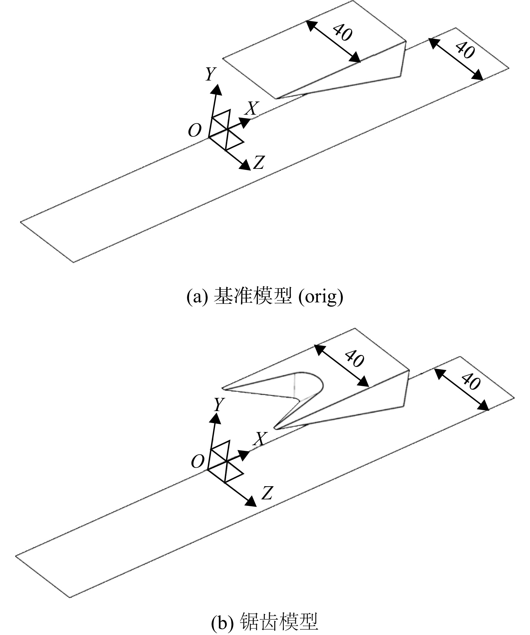
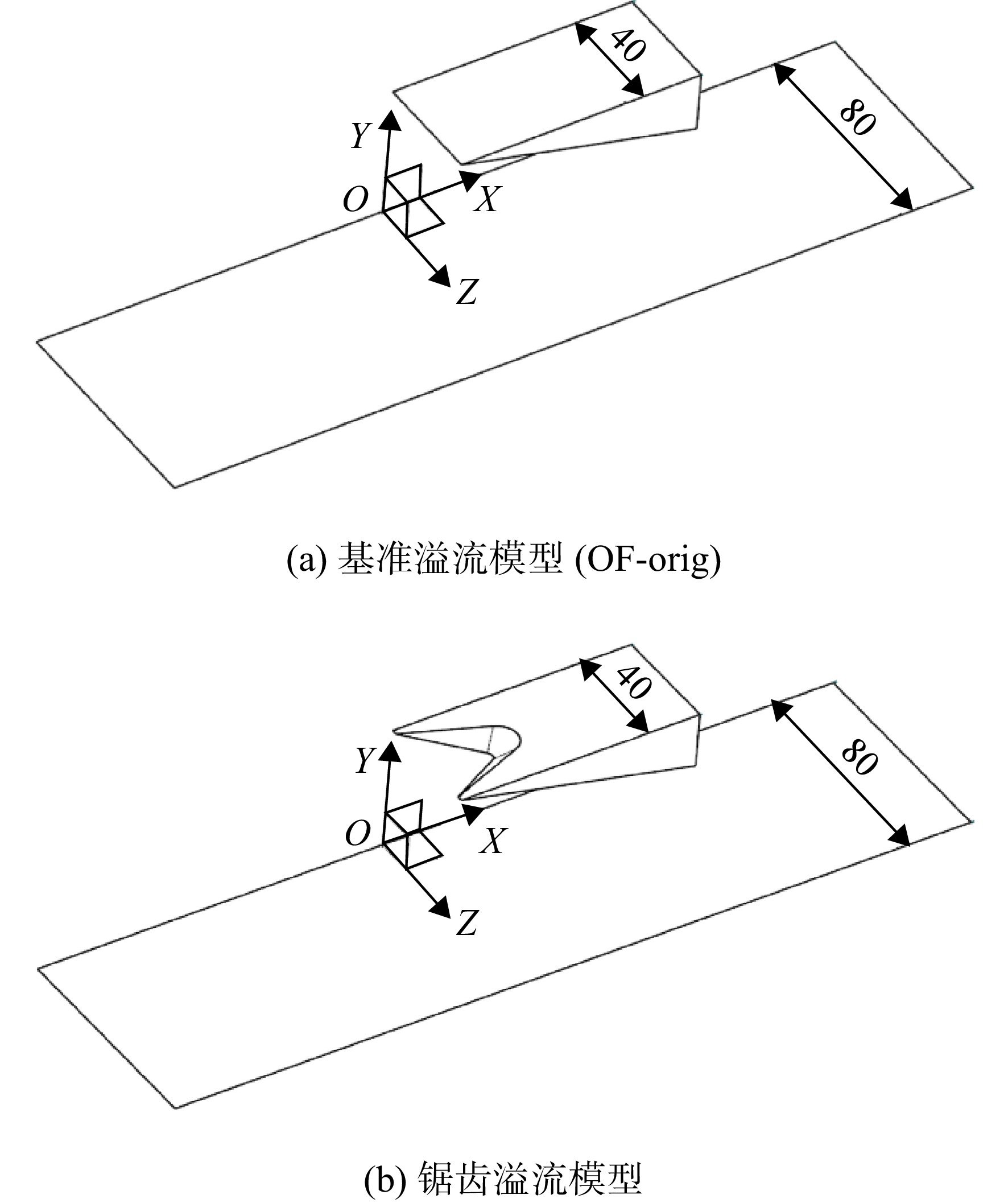
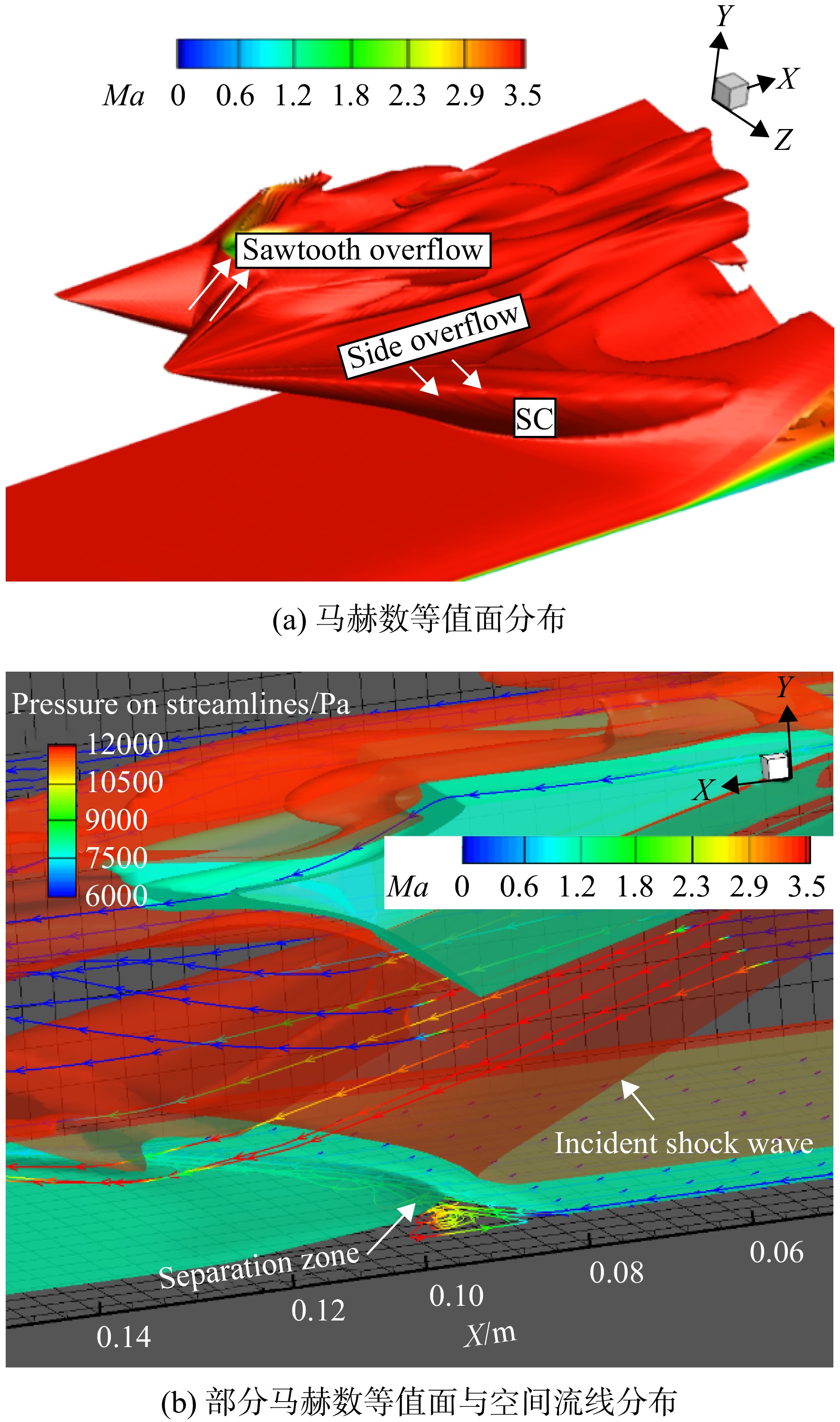
为探究三维锯齿构型对入射激波/边界层干扰流场结构的影响,对一种前缘带锯齿的斜楔/底板流场进行数值仿真分析,并总结了不同锯齿深度对流场的影响规律。结果表明:与前缘平直斜楔相比,锯齿斜楔受溢流的影响。入射激波呈现为三波系曲面结构,激波强度减弱,波角减小,流场结构后移;底板上分离区呈现出“凹”型的空间结构,分离区展向表现为中间低、两边高,流向表现为中间短,两边长。随着锯齿深度增大,流场结构更加后移,分离区的三维特性更加明显。在溢流模型中,受侧面溢流影响,对称面处的分离最大,分离区呈现出三维的“半凹”结构;对比基准溢流模型,锯齿溢流降低了入射波系强度,使侧面溢流减少。
Abstract:In order to investigate the influence of three-dimensional sawtooth configuration on the flow field structure of incident shock-wave/boundary-layer interaction, the flow field of wedge with sawtooth leading edge/plate was numerically simulated and analyzed, and the influence laws of different sawtooth depths on the flow field were summarized. The results showed that, compared with the wedge with straight leading edge, the sawtooth wedge was affected by overflow. Meanwhile, the incident shock wave presented a curved three-wave structure, the shock wave intensity was weakened, the wave angle was reduced, and the flow field structure moved backward; the separation zone on plate presented a “concave” spatial structure. The spreading direction of the separation zone was low in the middle but high on both sides, and the flow direction was short in the middle but long on both sides. With the increase of sawtooth depth, the flow field structure moved backward, and the three-dimensional characteristics of the separation zone became more obvious. In the overflow model, due to the side overflow, the separation at the symmetrical plane was the largest, and the separation zone presented a three-dimensional “semi concave” spatial structure. Compared with the original overflow model, the sawtooth overflow reduced the intensity of the incident wave system and the side overflow.
-

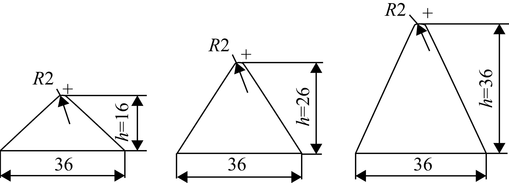
图 4 h=16,26,36 mm锯齿草图(单位:mm)
Figure 4. Sketch of sawtooth with h=16,26,36 mm (unit:mm)

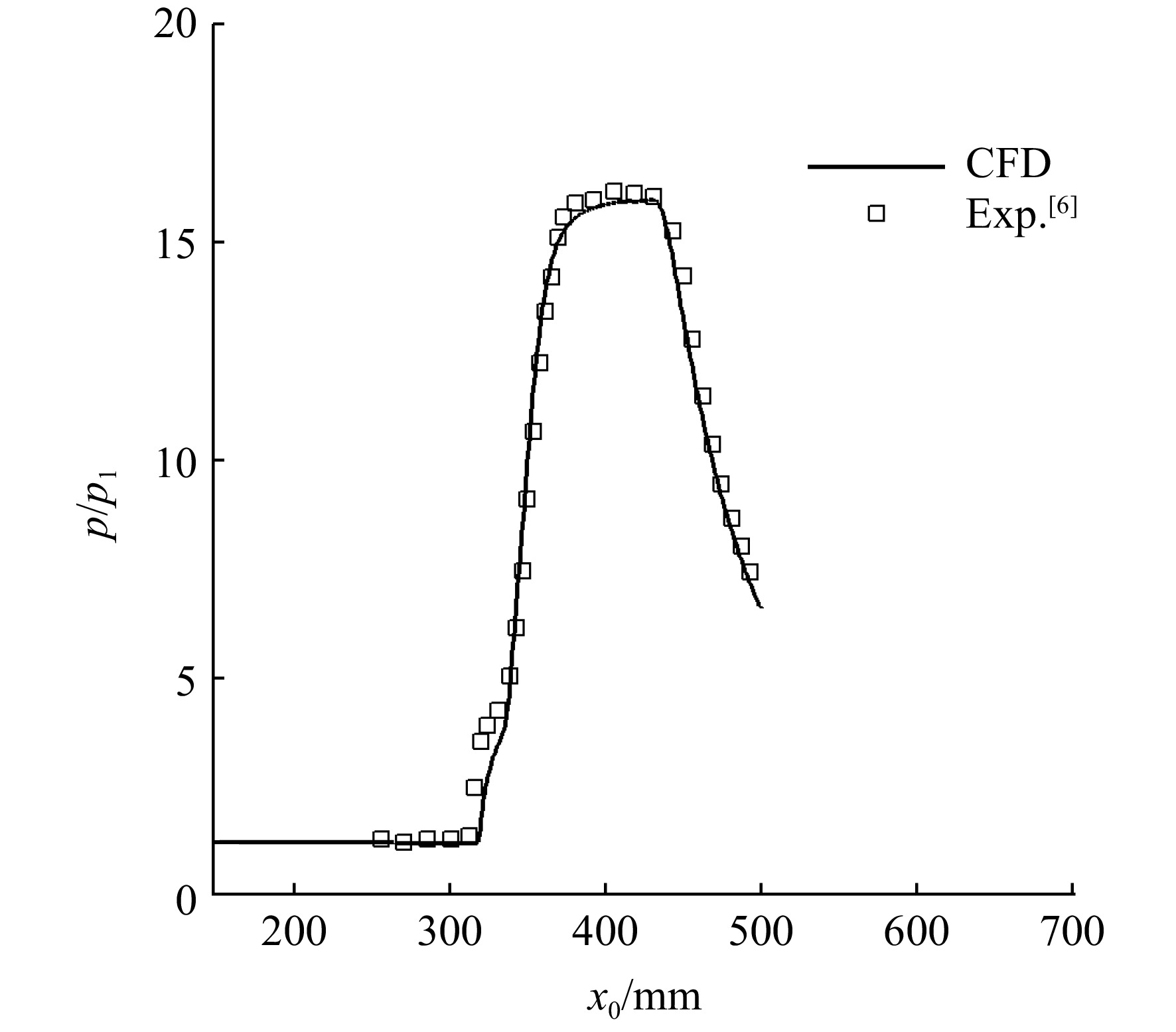
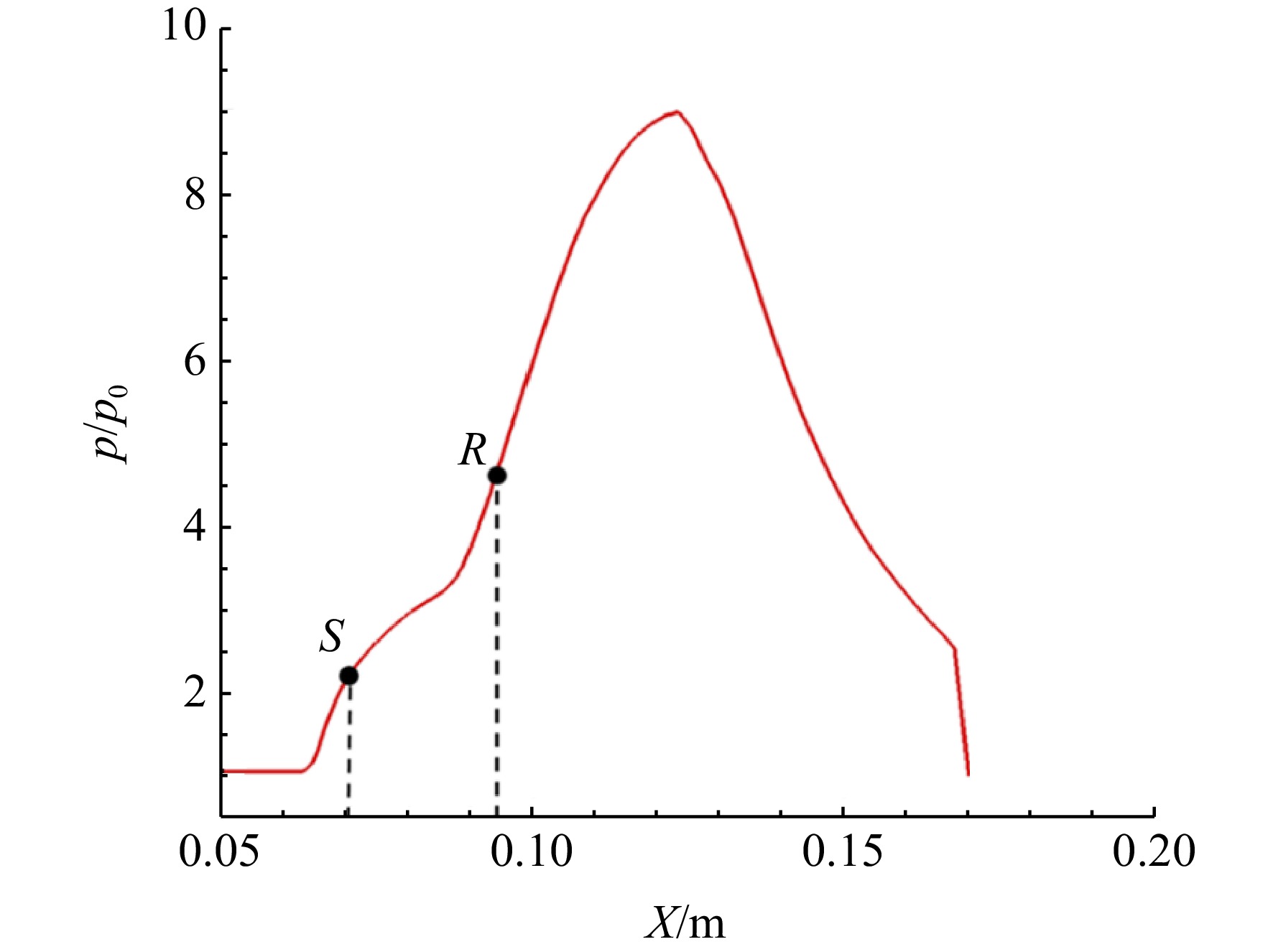
图 7 实验与仿真壁面压力分布对比
Figure 7. Comparison of wall pressure distribution between experiment and simulation

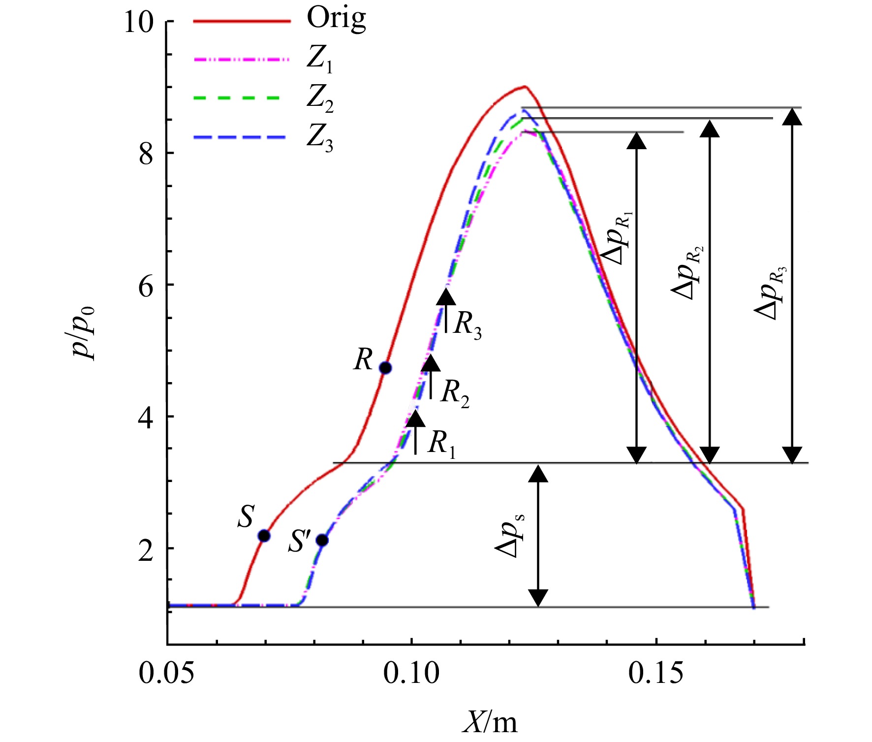
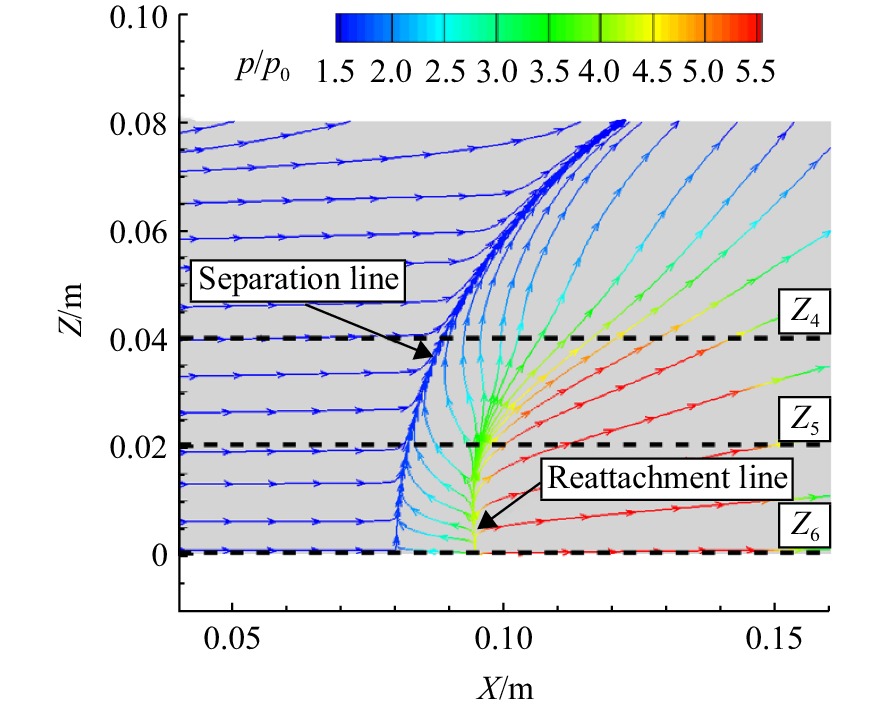
图 17 基准模型与h=36 mm锯齿模型Z1、Z2、Z3线上静压比分布曲线
Figure 17. Static pressure ratio distribution of original and h=36 mm sawtooth model on Z1, Z2, Z3

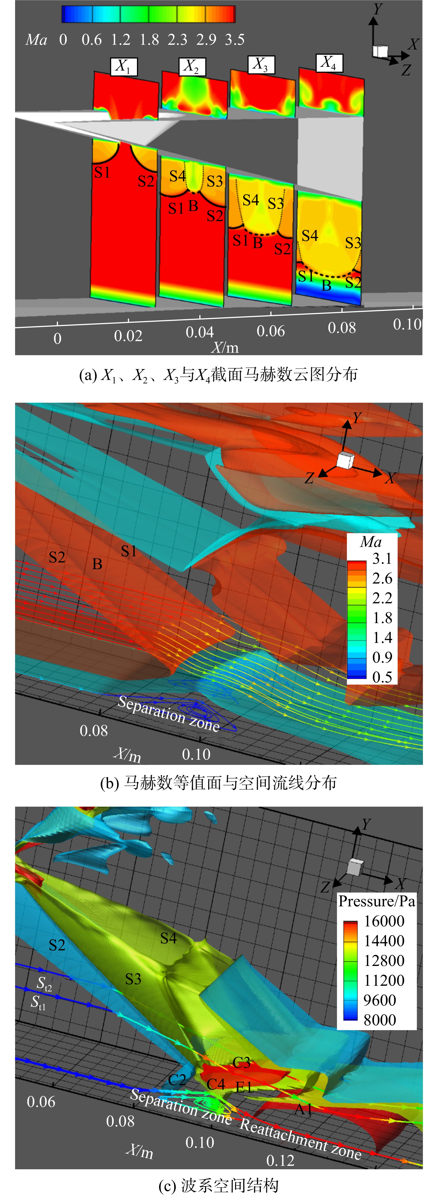
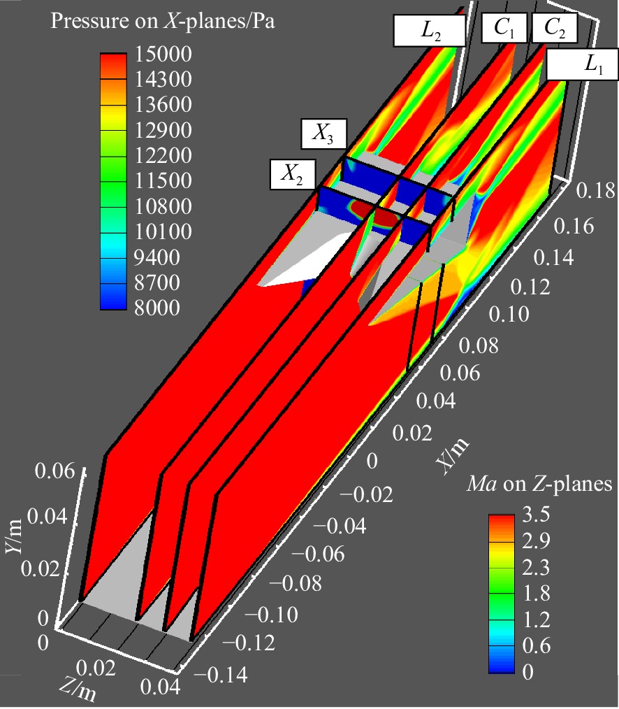
图 18 对称面L1、L2与面C1、C2、X2、X3分布
Figure 18. Distribution of symmetry planes L1, L2 and plane C1, C2, X2, X3

图 19 基准模型、h=16,26,36 mm模型在对称面L1和C1截面上马赫数云图
Figure 19. Mach number contours on symmetry plane L1 and C1 plans of original, h=16,26,36 mm models

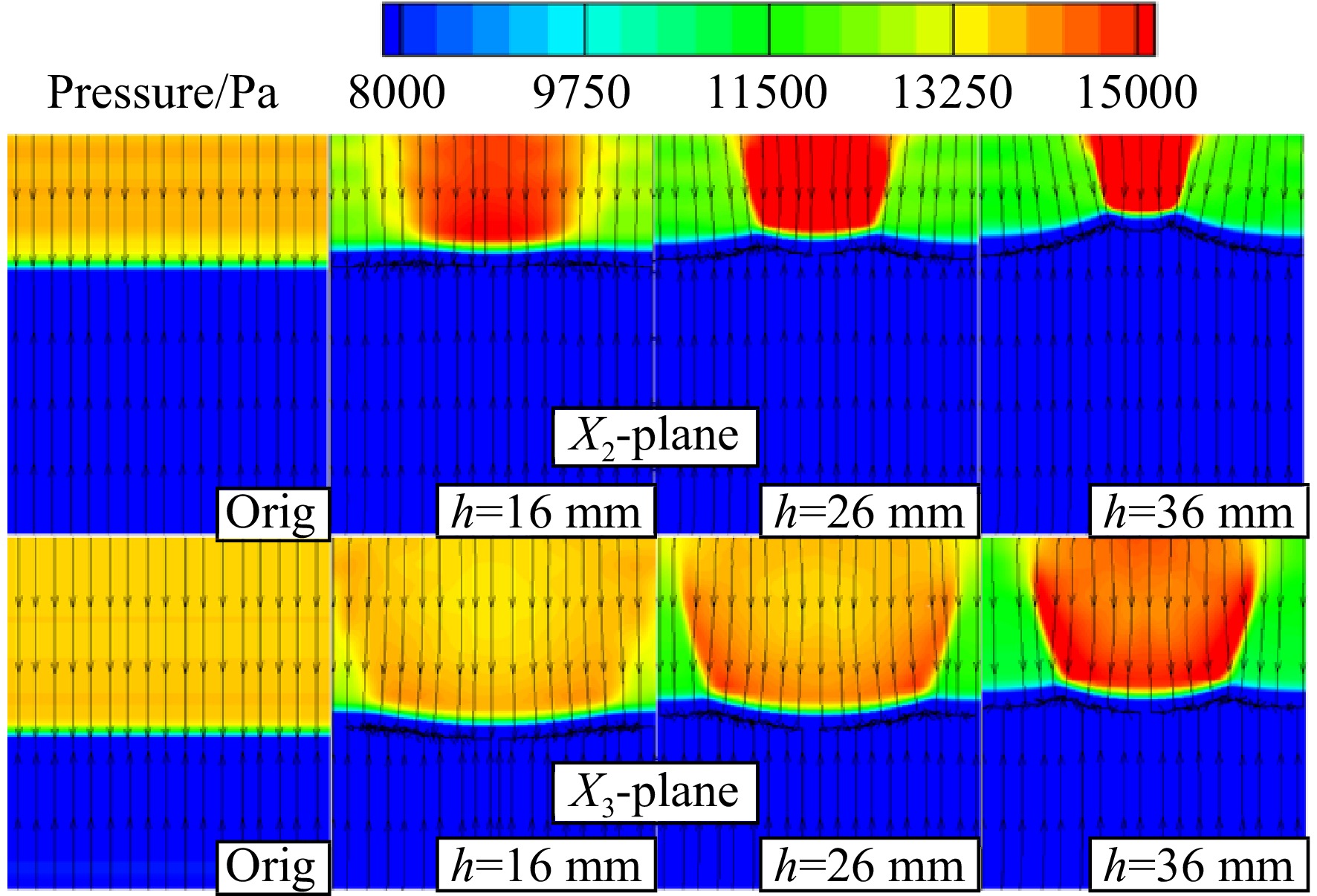
图 20 基准模型、h=16,26,36 mm在X2、X3截面上压力云图与流线分布
Figure 20. Pressure contour and streamlines on X2, X3 planes of original, h=16,26,36 mm model

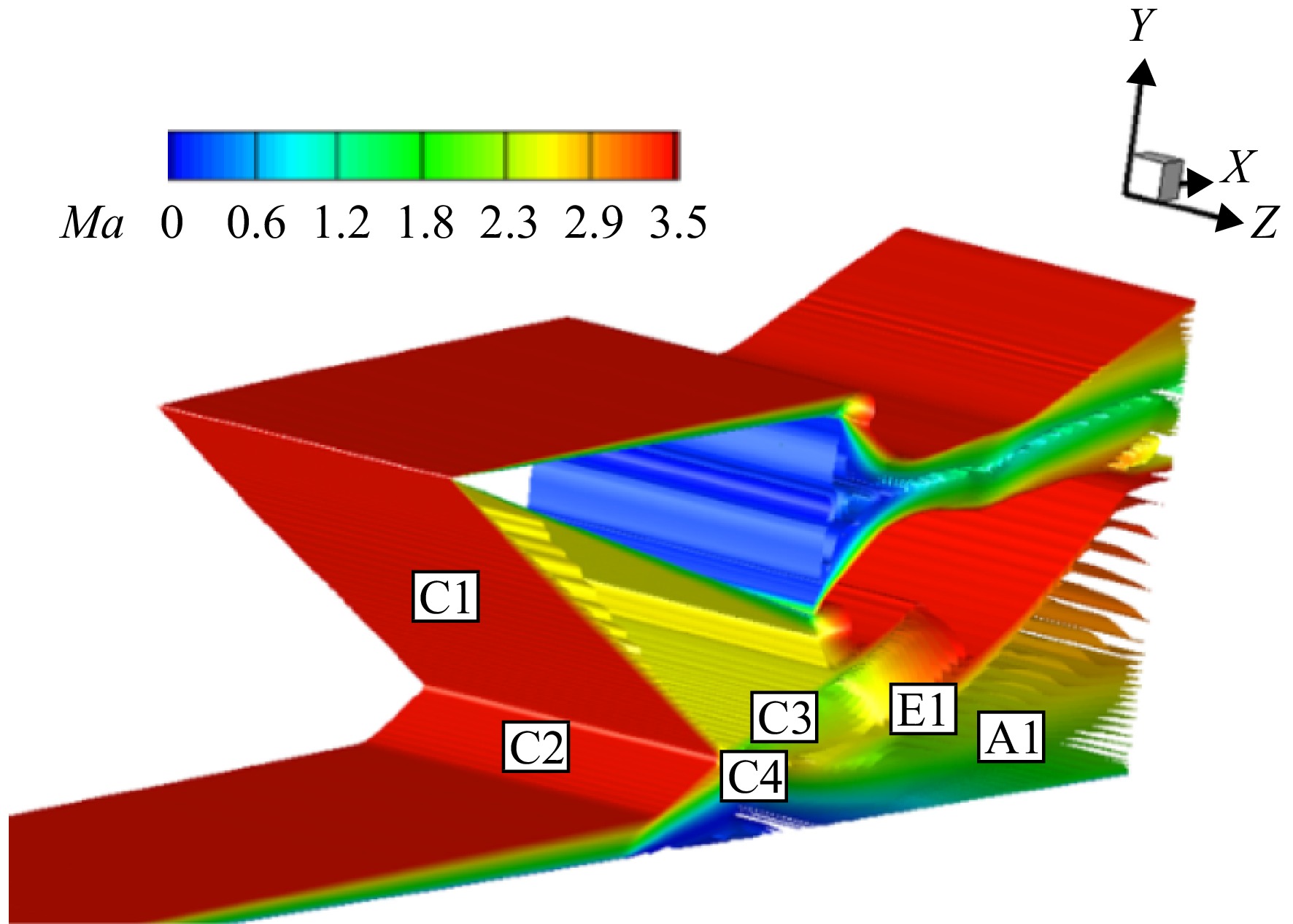
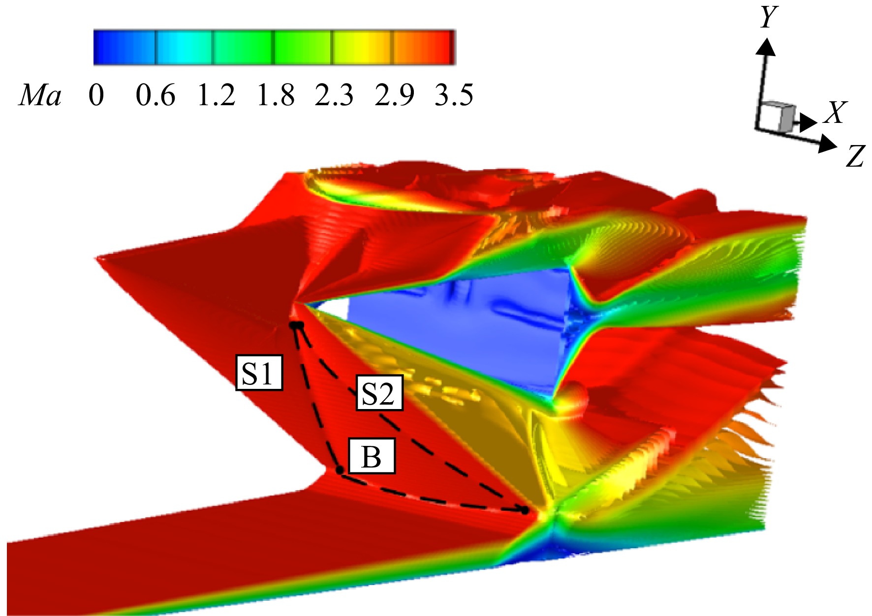
图 21 基准模型、h=16,26,36 mm模型底板静压云图与极限流线分布
Figure 21. Pressure contour and limiting streamlines on plates of original, h=16,26,36 mm model

图 22 基准模型、h=16,26,36 mm模型Z1线上静压比分布
Figure 22. Static pressure ratio distribution of original, h=16,26,36 mm models on Z1

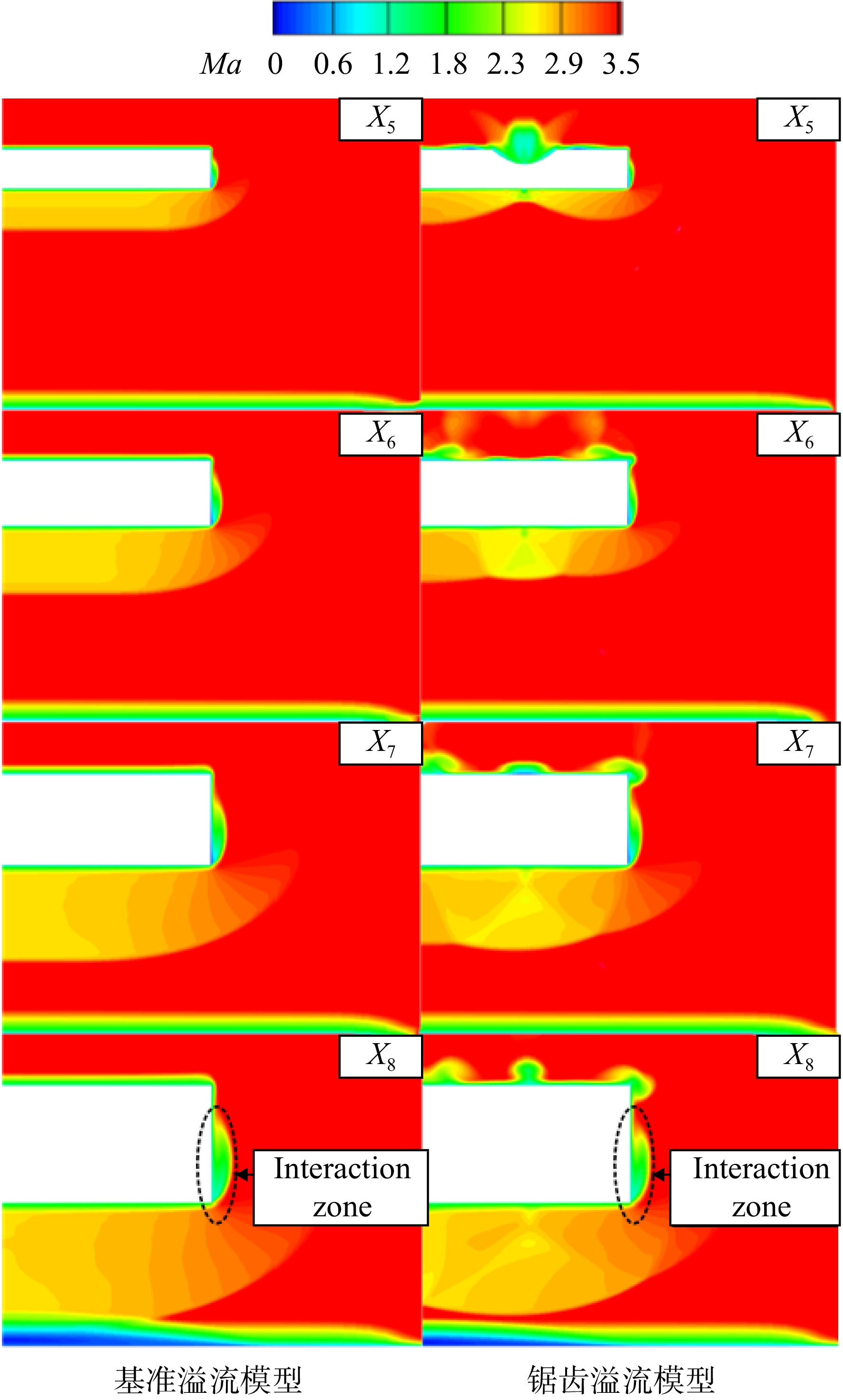
图 24 基准溢流模型与深度为26 mm锯齿溢流模型X5、X6、X7、X8截面马赫数云图
Figure 24. Mach number contours on X5, X6, X7 and X8 of original and 26 mm height overflow models

图 25 溢流模型底板表面极限流线与静压比分布
Figure 25. Limiting streamlines and static pressure ratio on plate of overflow model

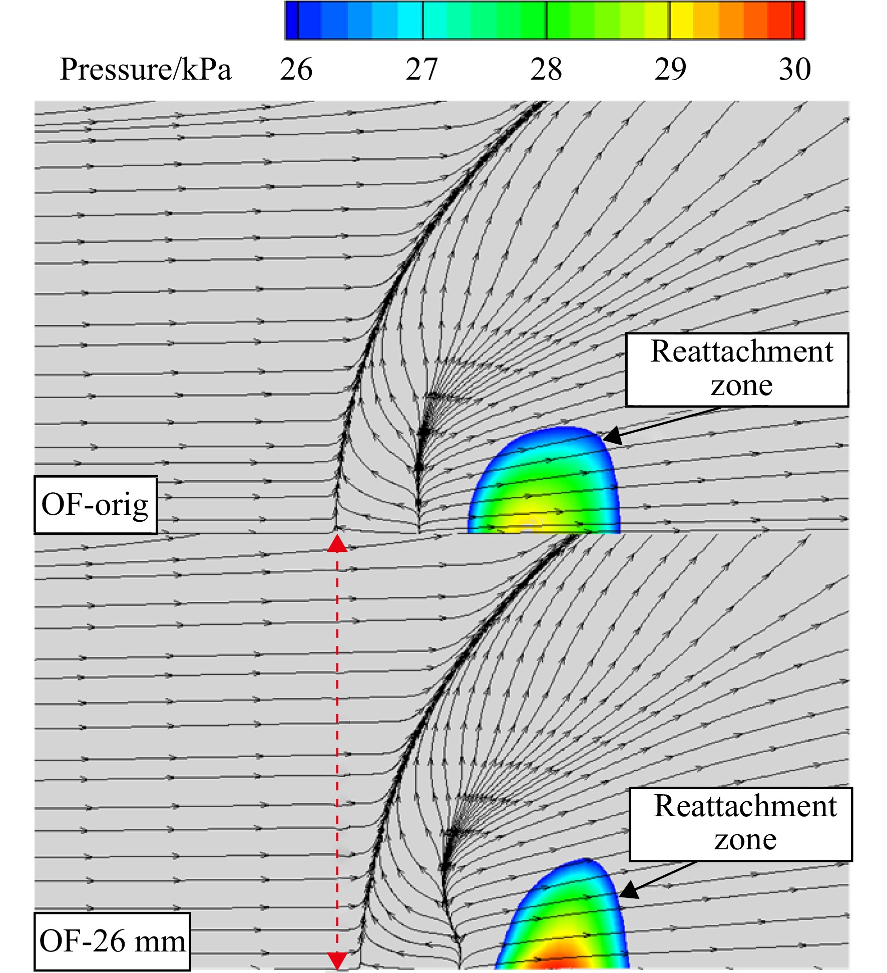
图 26 基准溢流模型与26 mm溢流模型底板再附区静压分布与极限流线
Figure 26. Limiting streamlines and static pressure on plate of OF-original and OF-26 mm models

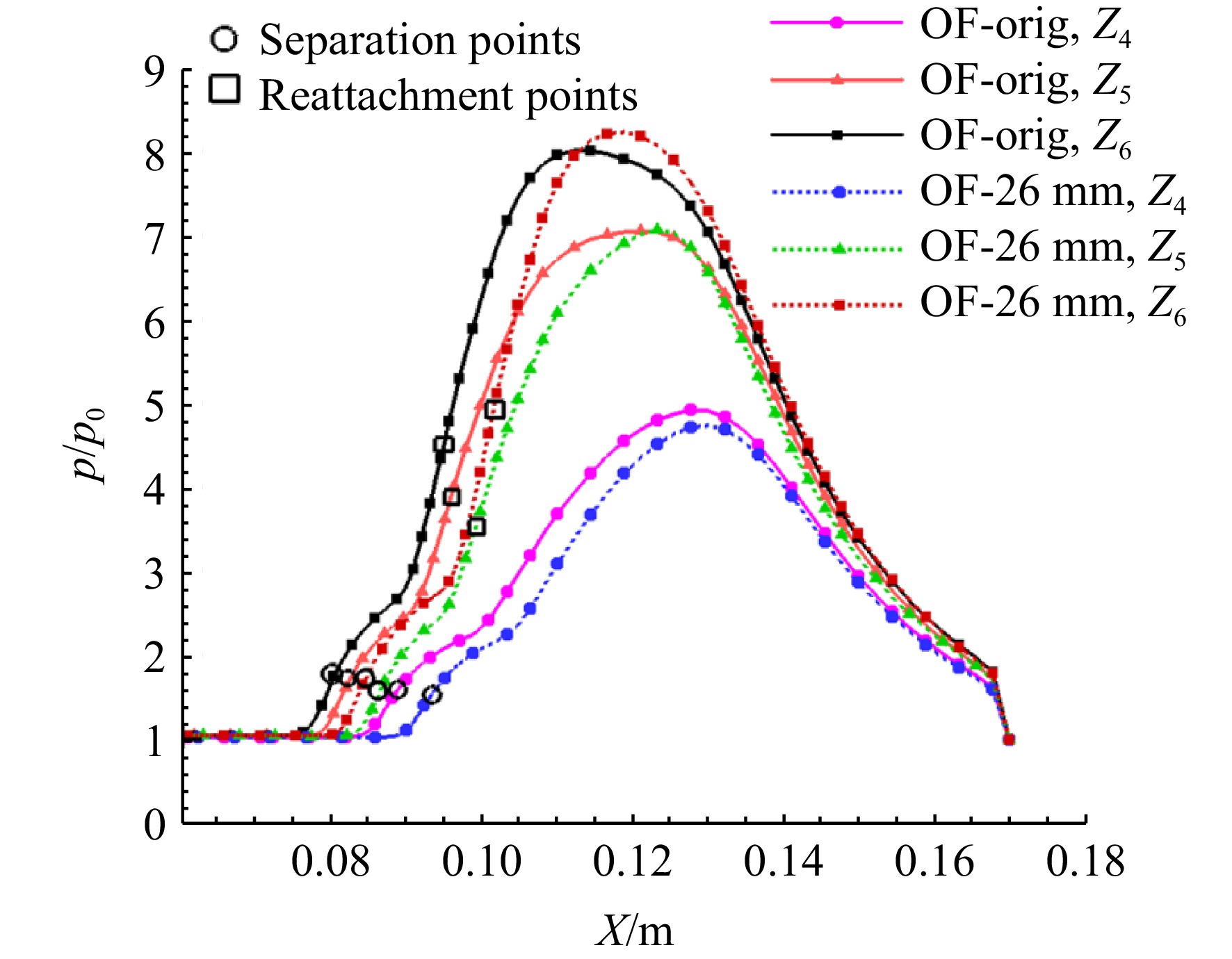
图 27 基准溢流模型与h=26 mm溢流模型Z4、Z5、Z6线静压比分布
Figure 27. Static pressure ratio on Z4, Z5, Z6 reference lines of OF-orig and OF-26 mm height models

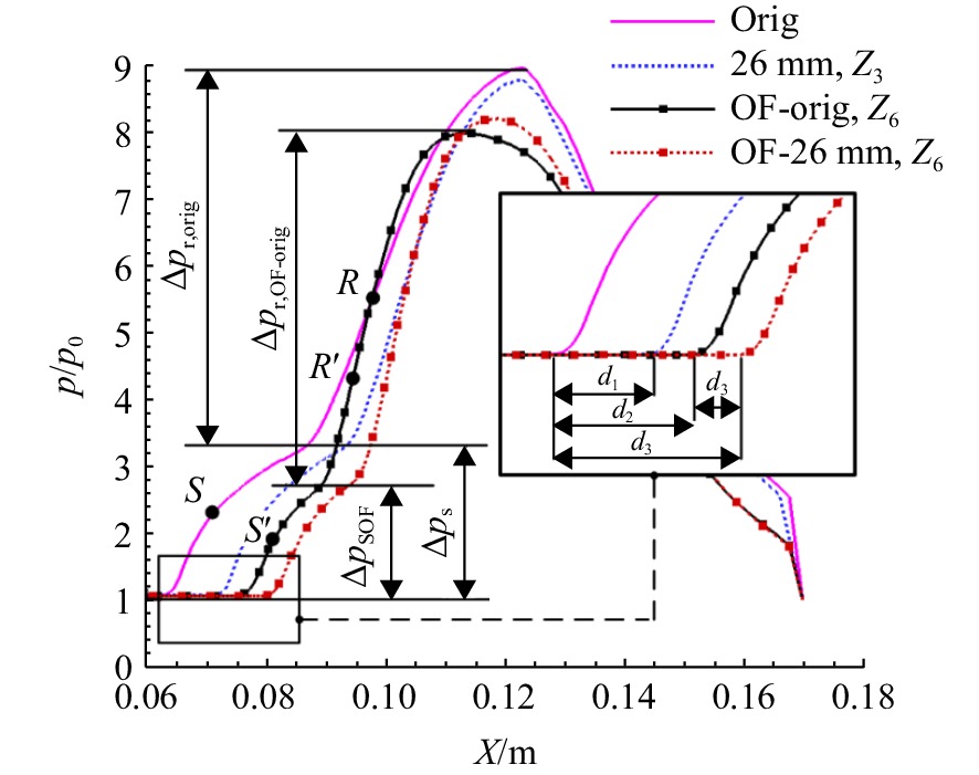
图 28 无限宽度模型Z3线与溢流模型Z6线静压比分布
Figure 28. Static pressure ratio distribution on Z3 of infinite width models and Z6 of overflow models
表 2 流场参数
Table 2. Flow field parameters
$ {Ma}_{\infty } $ ${p}_{0} $/Pa ${T}_{\infty } $/K p*/Pa 3.8 3645 122.05 422415.1  下载: 导出CSV
表 3 h=36 mm锯齿模型各分离流线上最大马赫数
Table 3. Maximum Mach number on separation streamlines of h=36 mm sawtooth model
参考平面 ${ {Ma}_{\mathrm{max}} }$ ${Z}_1^{'}$ 0.30 ${Z}_2^{'}$ 0.36 ${Z}_{3}^{'}$ 0.45
下载: 导出CSV
表 4 各模型分离区在平面上特征尺寸
Table 4. Characteristic size of separation zone on plane of different models
模型 分离高度/mm 分离跨度/mm L1 C1 L1 C1 Orig 3.91 3.91 28.60 28.60 h=5.8 mm 3.83 3.63 28.25 27.16 h=8 mm 3.81 3.53 27.72 26.30 h=16 mm 3.81 3.38 27.46 24.60 h=26 mm 3.80 2.86 27.43 23.16 h=36 mm 3.79 2.62 27.43 21.00
下载: 导出CSV
表 5 各模型溢流量
Table 5. Overflow rate of models
模型 质量流速/(kg/s) STOF SOF Orig h=26 mm 0.0105 OF-orig 0.0158 OF-26 mm 0.0105 0.0119
下载: 导出CSV
-
[1] BABINSKY H, HARVEY J K. Introduction[M]//BABINSKY H, HARVEY J K. Shock wave-boundary-layer interactions. Cambridge: Cambridge University Press, 2011: 1-4. [2] 黄舶. 高超声速内外流动激波/边界层相互作用的实验与数值研究[D]. 合肥: 中国科学技术大学, 2013.HUANG Bo. Experimental and numerical investigation of shock wave/boundary layer interaction in hypersonic flow[D]. Hefei: University of Science and Technology of China, 2013. (in Chinese) [3] ANDERSON G Y, MCCLINTON C R, WERDNER J P. Scramjet performance[M]. Reston, US: AIAA, 2000: 369-446. [4] DOLLING D S. Fifty years of shock-wave/boundary-layer interaction research-What next?[J]. AIAA Journal,2001,39(8): 1517-1531. doi: 10.2514/2.1476 [5] GAITONDE D V. Progress in shock wave/boundary layer interactions[J]. Progress in Aerospace Sciences,2015,72(1): 80-99. [6] SCHÜLEIN E. Skin friction and heat flux measurements in shock/boundary layer interaction flows[J]. AIAA Journal,2006,44(8): 1732-1741. doi: 10.2514/1.15110 [7] KORKEGI R H. A simple correlation for incipient-turbulent boundary-layer separation due to a skewed shock wave[J]. AIAA Journal,1973,11(11): 1578-1579. doi: 10.2514/3.50637 [8] MURRAY N,HILLIER R,WILLIAMS S. Experimental investigation of axisymmetric hypersonic shock-wave/turbulent-boundary-layer interactions[J]. Journal of Fluid Mechanics,2013,714: 152-189. doi: 10.1017/jfm.2012.464 [9] CLEMENS N T,NARAYANASWAMY V. Low-frequency unsteadiness of shock wave/turbulent boundary layer interactions[J]. Annual Review of Fluid Mechanics,2014,46: 469-492. doi: 10.1146/annurev-fluid-010313-141346 [10] 袁化成, 华正旭, 余安远. 高超声速进气道起动的物理过程及影响因素研究[C]//全国激波与激波管学术会议论文集. 洛阳: 中国力学学会激波与激波管委员会, 2016: 523-530. [11] BISEK N J. High-fidelity simulations of the HIFiRE-6 flow path at angle of attack[R]. AIAA 2016-4276, 2016. [12] STEELANT J, VARVILL R, DEFOORT S, et al. Achievements obtained for sustained hypersonic flight within the LAPCAT project[R]. AIAA 2015-3677, 2015. [13] 王翼. 高超声速进气道启动问题研究[D]. 长沙: 国防科学技术大学, 2008.WANG Yi. Investigation on the starting characteristics of hypersonic inlet[D]. Changsha: National University of Defense Technology, 2008. (in Chinese) [14] 石磊,何国强,秦飞,等. 唇口形状对二元进气道性能影响数值模拟[J]. 推进技术,2012,33(5): 683-688. doi: 10.13675/j.cnki.tjjs.2012.05.002SHI Lei,HE Guoqiang,QIN Fei,et al. Numerical investigation of effects of cowl lip shape on 2-D inlet[J]. Journal of Propulsion Technology,2012,33(5): 683-688. (in Chinese) doi: 10.13675/j.cnki.tjjs.2012.05.002 [15] 郭金默,谢旅荣,李晓驰,等. 一种锯齿状唇口超声速轴对称进气道特性[J]. 航空动力学报,2021,36(2): 264-274. doi: 10.13224/j.cnki.jasp.2021.02.005GUO Jinmo,XIE Lyurong,LI Xiaochi,et al. Characteristics of a supersonic axisymmetric inlet with saw tooth lip[J]. Journal of Aerospace Power,2021,36(2): 264-274. (in Chinese) doi: 10.13224/j.cnki.jasp.2021.02.005 [16] 金志光,张堃元. 高超侧压式进气道简单唇口调节方案设计[J]. 推进技术,2008,29(1): 43-48. doi: 10.3321/j.issn:1001-4055.2008.01.010JIN Zhiguang,ZHANG Kunyuan. Concept of a varied geometry scramjet inlet with rotatable cowl[J]. Journal of Propulsion Technology,2008,29(1): 43-48. (in Chinese) doi: 10.3321/j.issn:1001-4055.2008.01.010 [17] XIAO Fengshou,LI Zhufei,ZHANG Zhiyu,et al. Hypersonic shock wave interactions on a V-shaped blunt leading edge[J]. AIAA Journal,2018,56(1): 356-367. doi: 10.2514/1.J055915 [18] 蒙泽威,范晓樯,陶渊,等. 三维内收缩式进气道V形溢流口热流计算与分析[J]. 推进技术,2018,39(8): 1737-1743. doi: 10.13675/j.cnki.tjjs.2018.08.007MENG Zewei,FAN Xiaoqiang,TAO Yuan,et al. Investigation of aerothermal heating on V-shaped leading edge of inward turning inlet[J]. Journal of Propulsion Technology,2018,39(8): 1737-1743. (in Chinese) doi: 10.13675/j.cnki.tjjs.2018.08.007 [19] 张恩来,李祝飞,李一鸣,等. 斜激波入射V形钝前缘溢流口激波干扰研究[J]. 实验流体力学,2018,32(3): 50-57. doi: 10.11729/syltlx20180002ZHANG Enlai,LI Zhufei,LI Yiming,et al. Investigation on the shock interactions between an incident shock and a plate with V-shaped blunt leading edge[J]. Journal of Experiments in Fluid Mechanics,2018,32(3): 50-57. (in Chinese) doi: 10.11729/syltlx20180002 [20] LI Yiming, LI Zhufei, YANG Jiming, et al. Visualization of hypersonic inward-turning inlet flows by planar laser scattering method[R]. AIAA 2017-2358, 2017. [21] BABINSKY H, HARVEY J. Shock wave-boundary-layer interactions[M]. Cambridge, UK: Cambridge University Press, 2011. -


 点击查看大图

计量
- 文章访问数: 43
- HTML浏览量: 15
- PDF量: 12
- 被引次数: 0