


Analysis of blade cooling performance based on improved temperature assessment model
-
摘要:
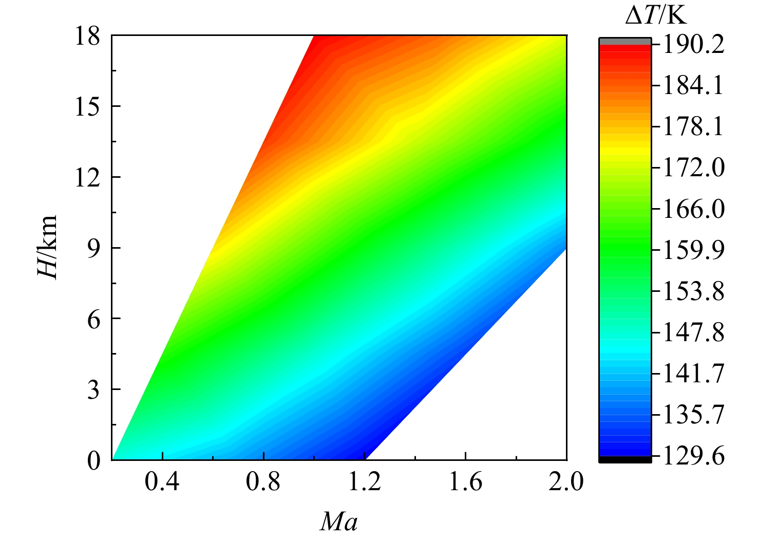
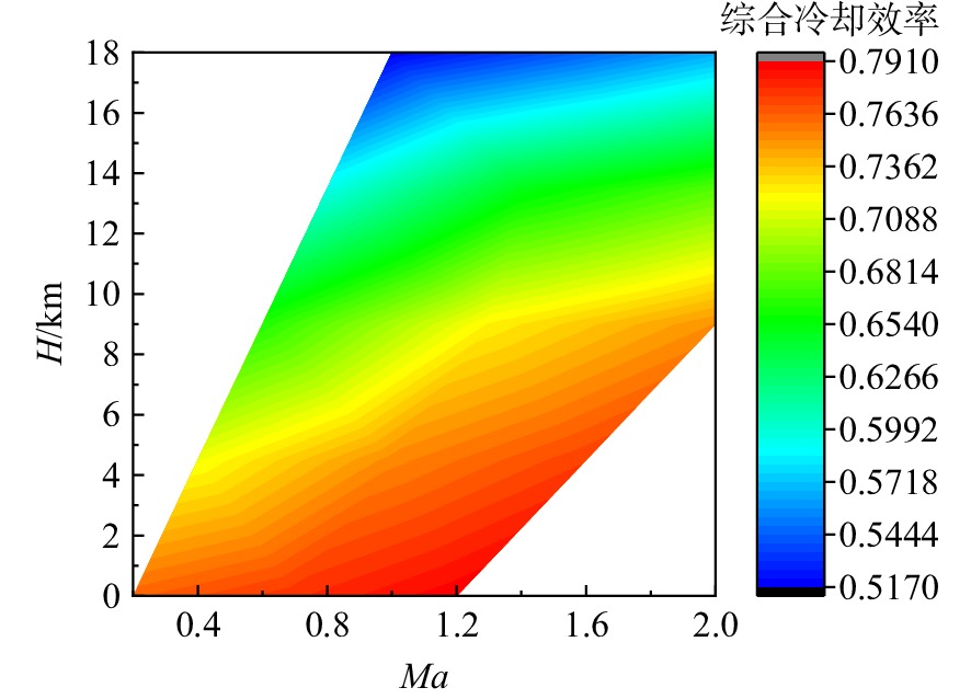
为适应航空发动机涡轮冷却技术的发展趋势,在传统叶片温度评估模型的基础上加以改进,提出了适用于内外耦合涡轮叶片的温度评估模型。将改进后的温度评估模型嵌入到发动机整机热力性能计算模型中,对飞机/发动机系统耦合分析,研究了F-16战机在典型飞行任务和飞行包线内高压涡轮导叶的冷却性能。结果表明:在全飞行任务下进行分析时,叶片在实用升限、起飞及大爬升率工况下叶片工作热环境恶劣,叶片易超温;叶片表面温度沿径向为增长趋势,在叶顶处达到最大值。在全飞行包线内进行分析时,叶片表面温度随高度变化明显;包线内高空低马赫数区域叶片的最高温度和承受的热应力最大,叶片最高温度可达1342 K;高空低马赫数区域的综合冷却效率与包线内的最高冷却效率相比,降低了34.2%,叶片冷却性能下降明显。在进行模型参数敏感性分析时,与基准方案相比,当输入参数改变相同比例,改变冷气进口温度对叶片温度的影响最为显著。
Abstract:In order to meet the development trend of aero-engine turbine cooling technology, based on the traditional blade temperature evaluation model, an improved model suitable for internal and external coupled turbine blades was proposed. The improved temperature evaluation model was embedded into the engine thermal performance calculation model. And the cooling performance of the high pressure turbine guide vane of F-16 fighter within typical flight missions and flight envelope was studied through the coupling analysis of aircraft and engine. Results showed that: when analyzed on the whole flight mission, under the conditions of practical lift limit, take-off and high climb rate, the blade worked in bad thermal environment and was prone to overheat; the blade surface temperature increased along the radial direction and reached the maximum value at the blade tip. When analyzed in the flight envelope, the blade temperature changed obviously with the height; the maximum temperature and thermal stress of the blade in the high altitude region with low Mach number were the largest, and the maximum temperature of the blade can reach 1342 K; compared with the highest cooling efficiency in flight envelope, the comprehensive cooling efficiency in the high altitude region with low Mach number was reduced obviously by 34.2%. When conducting sensitivity analysis of model parameters, compared with the benchmark scheme, when the input parameters changed by the same proportion, changing the inlet temperature of cool air had the most significant effect on blade temperature.
-
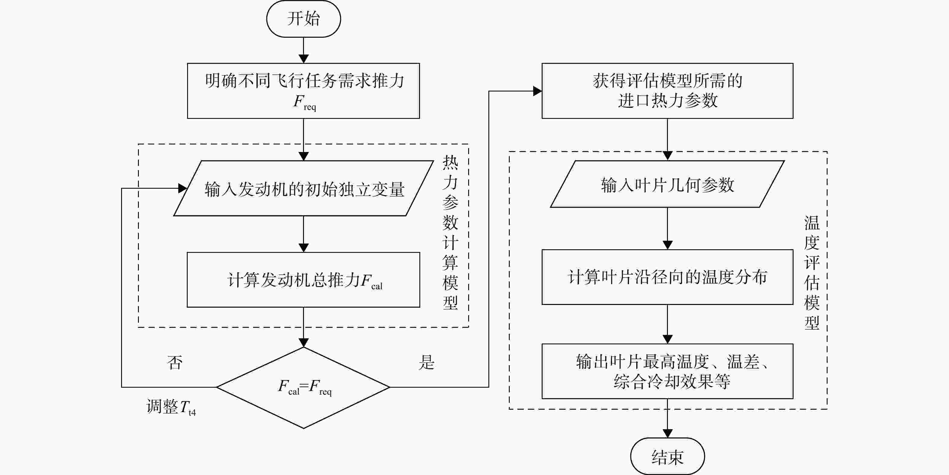
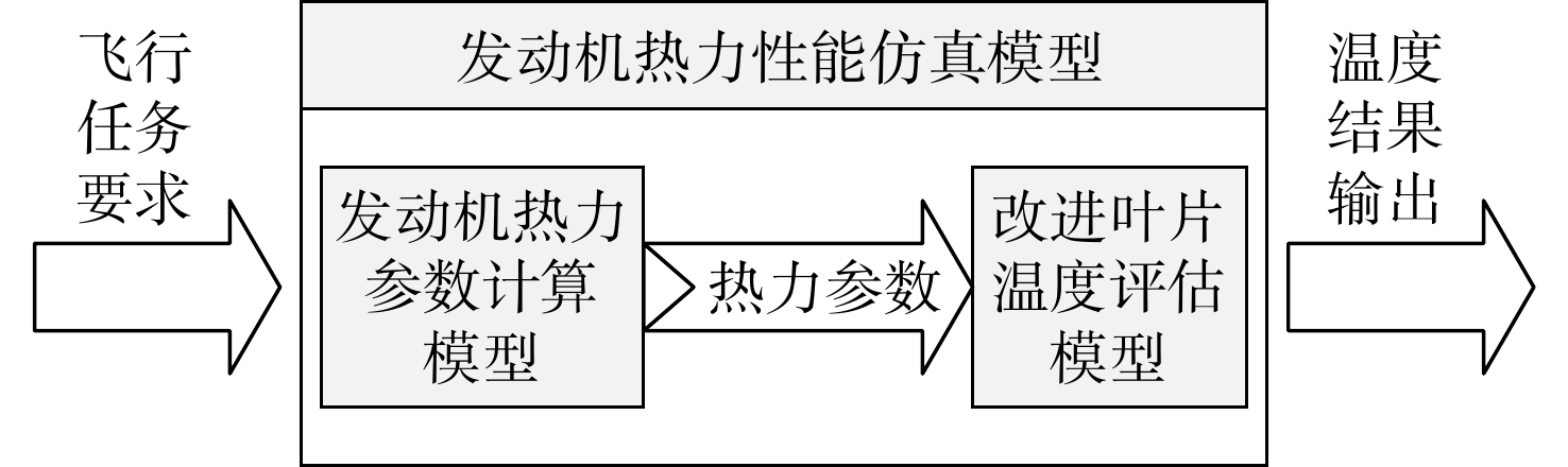
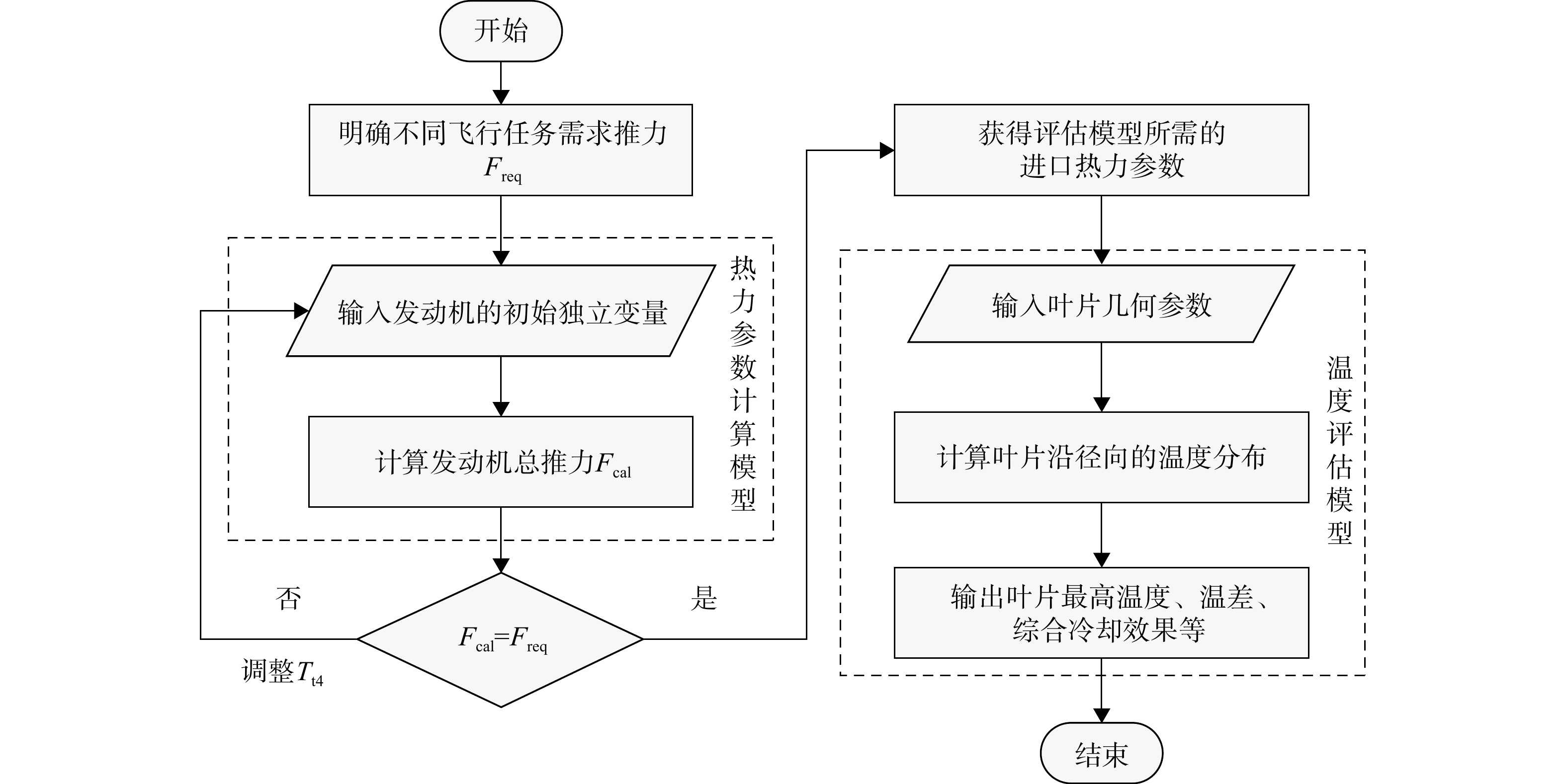
图 3 飞行任务下叶片冷却性能评估流程
Figure 3. Evaluation process of blade cooling performance under flight mission
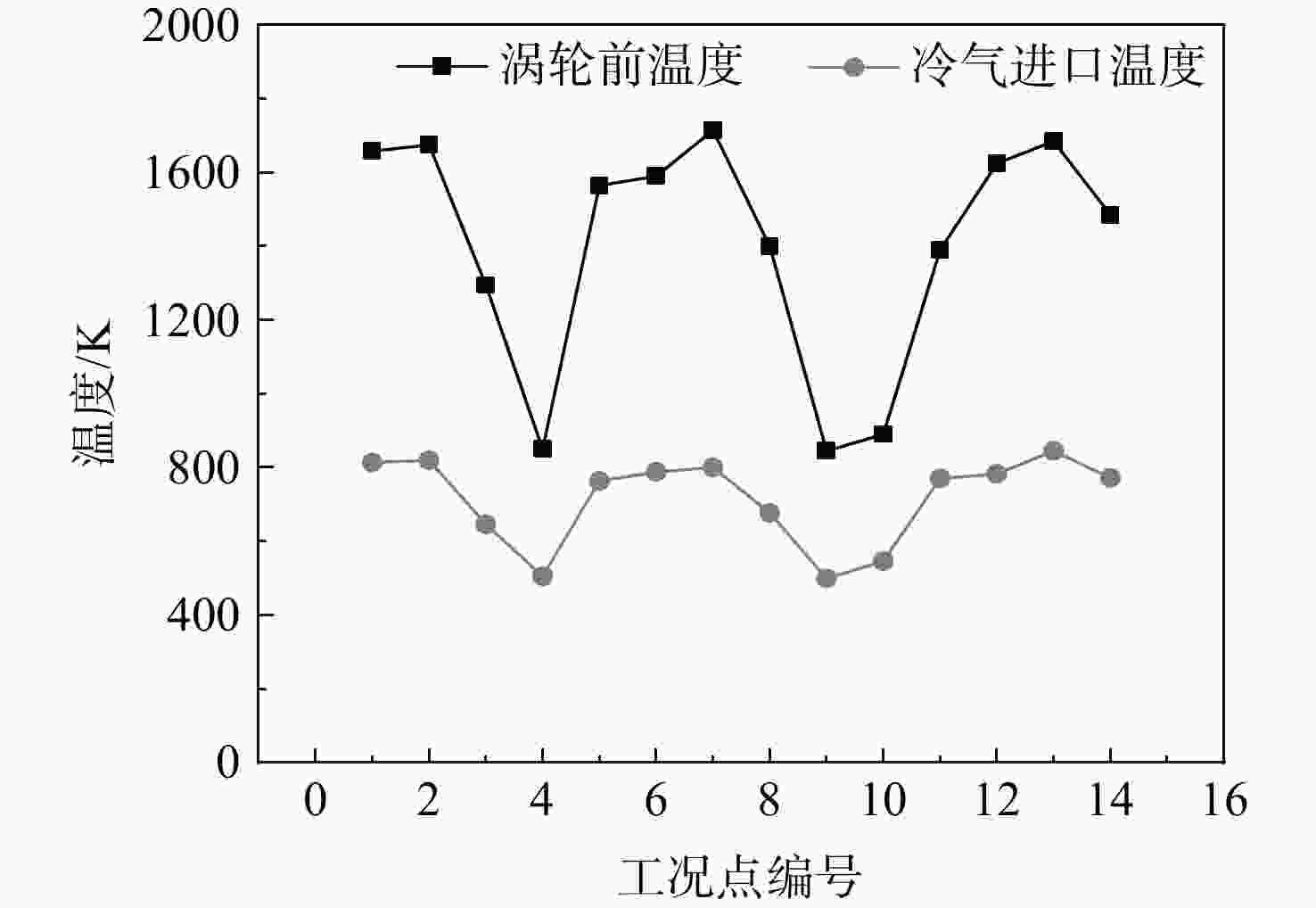
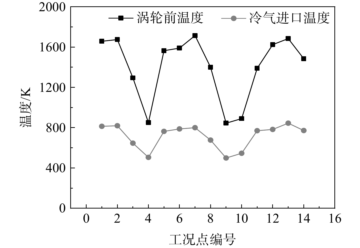
图 11 各飞行工况涡轮前温度及冷气进口温度
Figure 11. Turbine front temperature and air inlet temperature in each flight condition

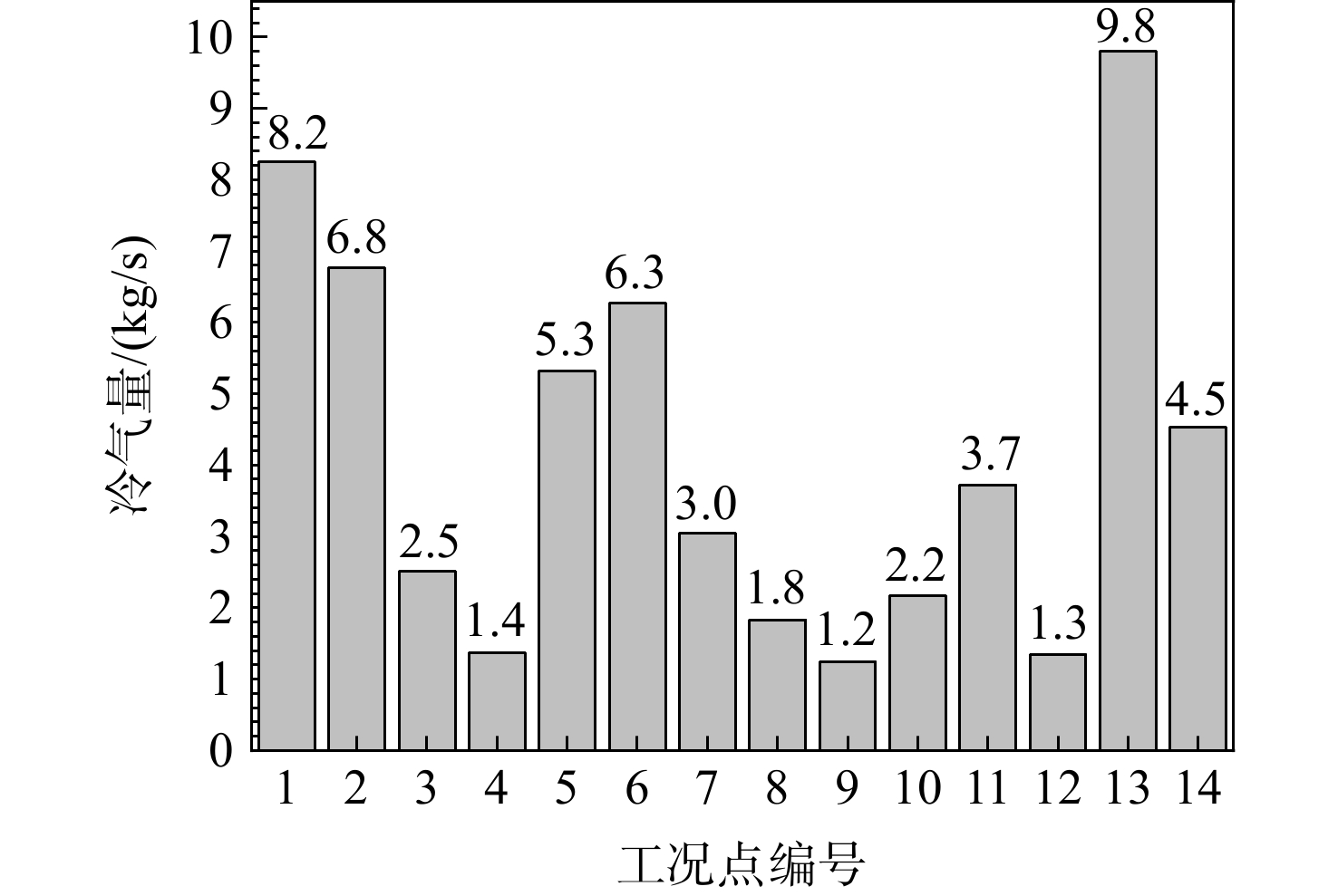
图 12 各飞行工况下叶片进口冷气量
Figure 12. Flow rate of cool air at blade inlet in each flight condition
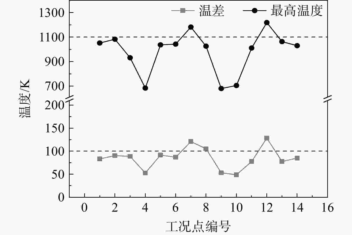
图 13 不同飞行任务叶片外表面最高温度及温差
Figure 13. Maximum temperature and temperature difference of blade surface in different flight missions
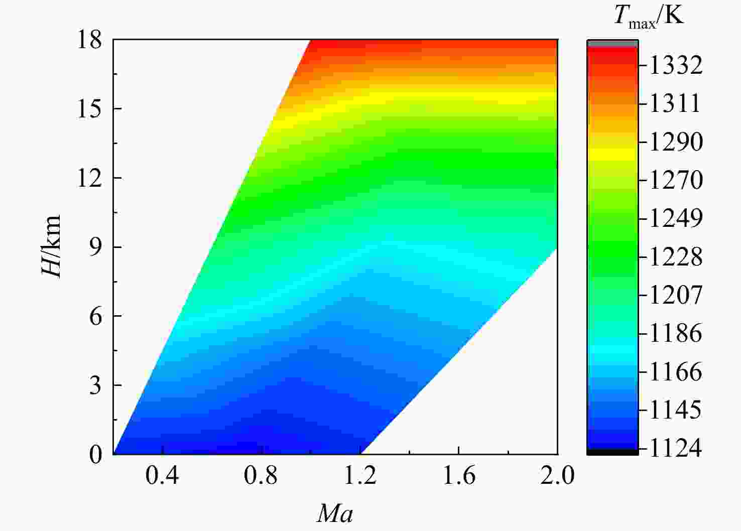
图 16 包线内叶片表面最高温度分布
Figure 16. Maximum temperature distribution on blade surface in envelope
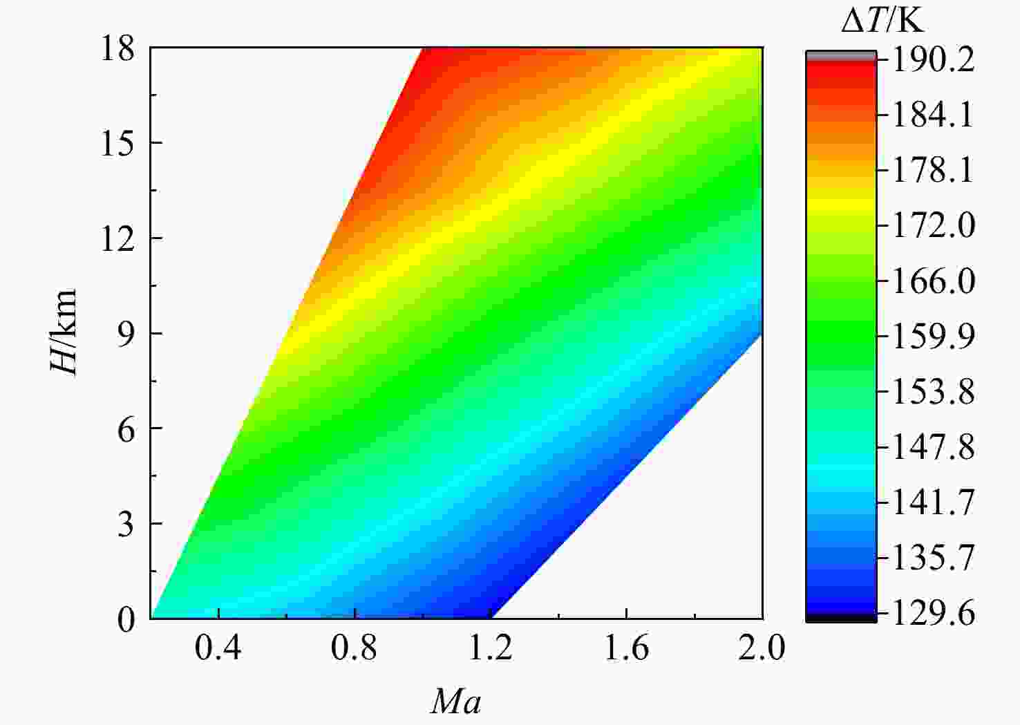
图 17 包线内叶片表面温差分布
Figure 17. Temperature difference distribution on blade surface in envelope

图 18 包线内叶片综合冷却效率分布
Figure 18. Blade comprehensive cooling efficiency distribution in envelope
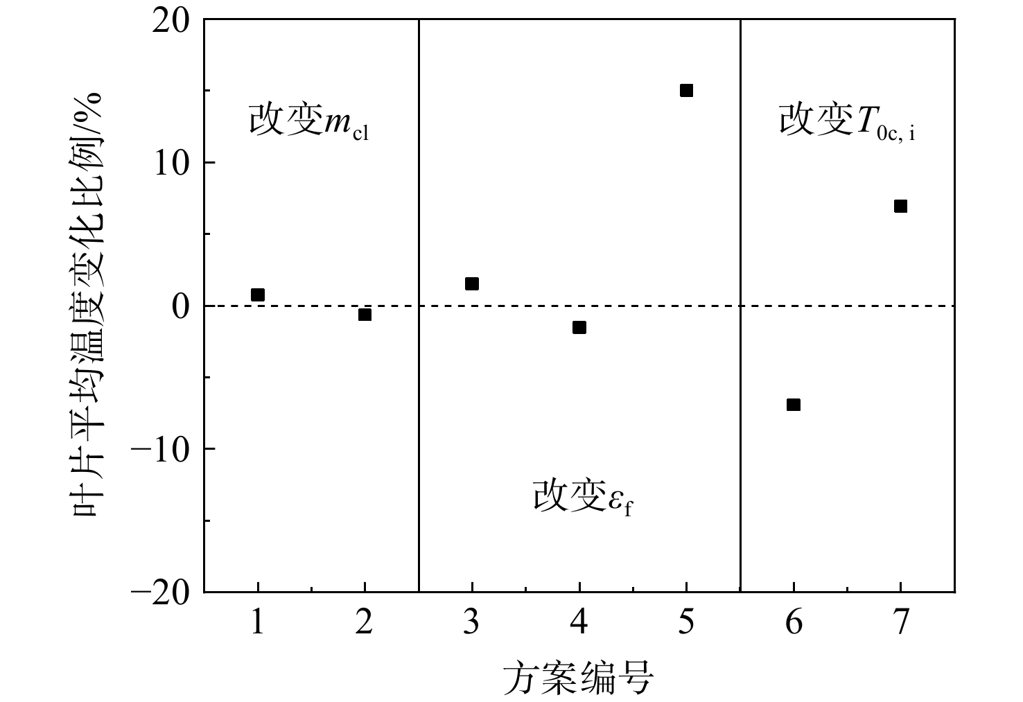
图 20 与基准方案相比叶片表面温度变化
Figure 20. Changes in blade surface temperature compared with the reference scheme
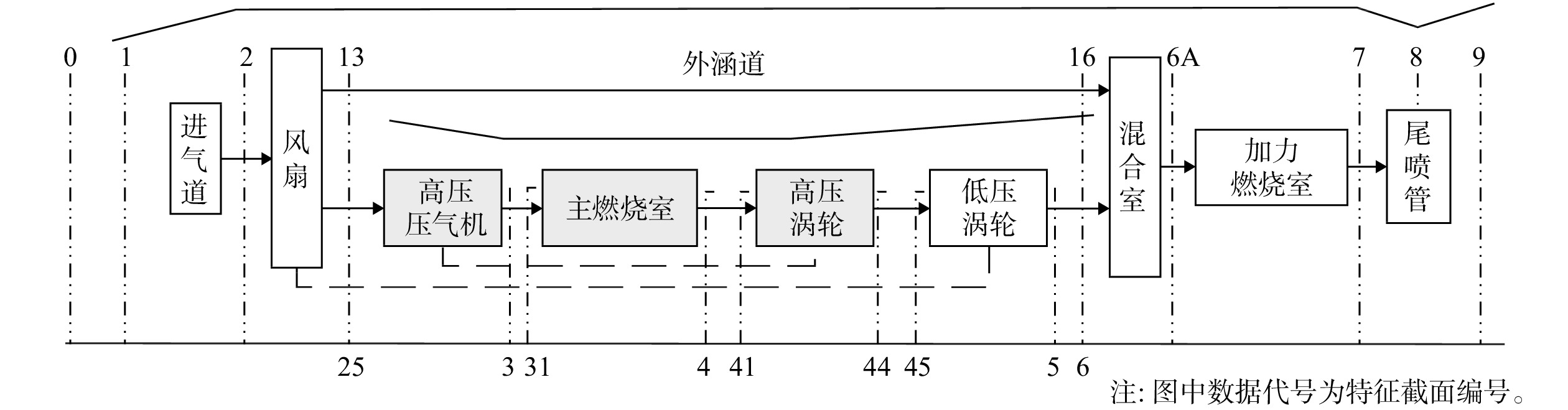
表 1 特征截面
Table 1. Characteristic of section
编号 截面含义 编号 截面含义 0-0 远前方来流 44-44 高压涡轮出口 1-1 进气道进口 45-45 低压涡轮转子进口 2-2 风扇进口 5-5 低压涡轮出口 13-13 风扇出口 6-6 混合室主流进口 25-25 高压压气机进口 16-16 混合室外涵气流进口 3-3 高压压气机出口 6A-6A 加力燃烧室进口 31-31 燃烧室进口 7-7 尾喷管进口 4-4 燃烧室出口 8-8 尾喷管喉道 41-41 高压涡轮转子进口 9-9 尾喷管出口  下载: 导出CSV
表 2 F-119发动机循环参数
Table 2. Cycle parameters of the F-119 engine
循环参数 设计点(H=0 km、Ma=0) 非设计点(H=11 km、Ma=1.5) 换算空气流量/(kg/s) 126 125.52 涵道比 0.3 0.298 风扇压比 4.5 4.5 风扇效率 0.85 0.8549 压气机压比 5.8 5.786 压气机效率 0.86 0.8613 涡轮前温度/K 1860 2011 高压涡轮效率 0.87 0.875 低压涡轮效率 0.88 0.8845 高压导叶引气比例/% 12 12 高压动叶引气比例/% 7.2 7.2 低压导叶引气比例/% 5.5 5.5 飞机系统引气比例/% 1 1
下载: 导出CSV
表 3 F-119发动机设计点验证
Table 3. Validation of the F-119 engine design points
参数 设计点(H=0 km、 Ma=0) 文献[11] 计算值 GASTURB 推力/kN 105.5 105.0 105.5 耗油率/(kg/(N·h)) 0.0837 0.0866 0.0836 高压涡轮膨胀比 2.660 2.820 2.719 低压涡轮膨胀比 2.110 2.102 2.072 喉道面积/m2 0.2448 0.2501 0.2450
下载: 导出CSV
表 4 F-119发动机非设计点验证
Table 4. Validation of the F-119 engine off-design points
参数 非设计点(H=11 km、Ma=1.5) 文献[11] 计算值 GASTURB 推力/kN 62.5 65.4 62.49 耗油率/(kg/(N·h)) 0.1183 0.1127 0.1190 高压涡轮膨胀比 2.660 2.782 2.711 低压涡轮膨胀比 2.100 2.081 2.073 喉道面积/m2 0.2448 0.2571 0.2479
下载: 导出CSV
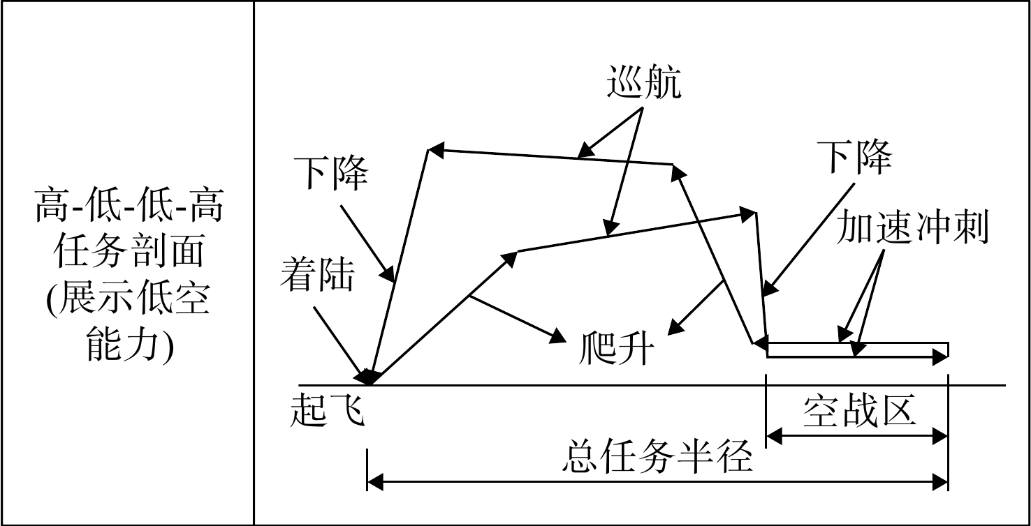
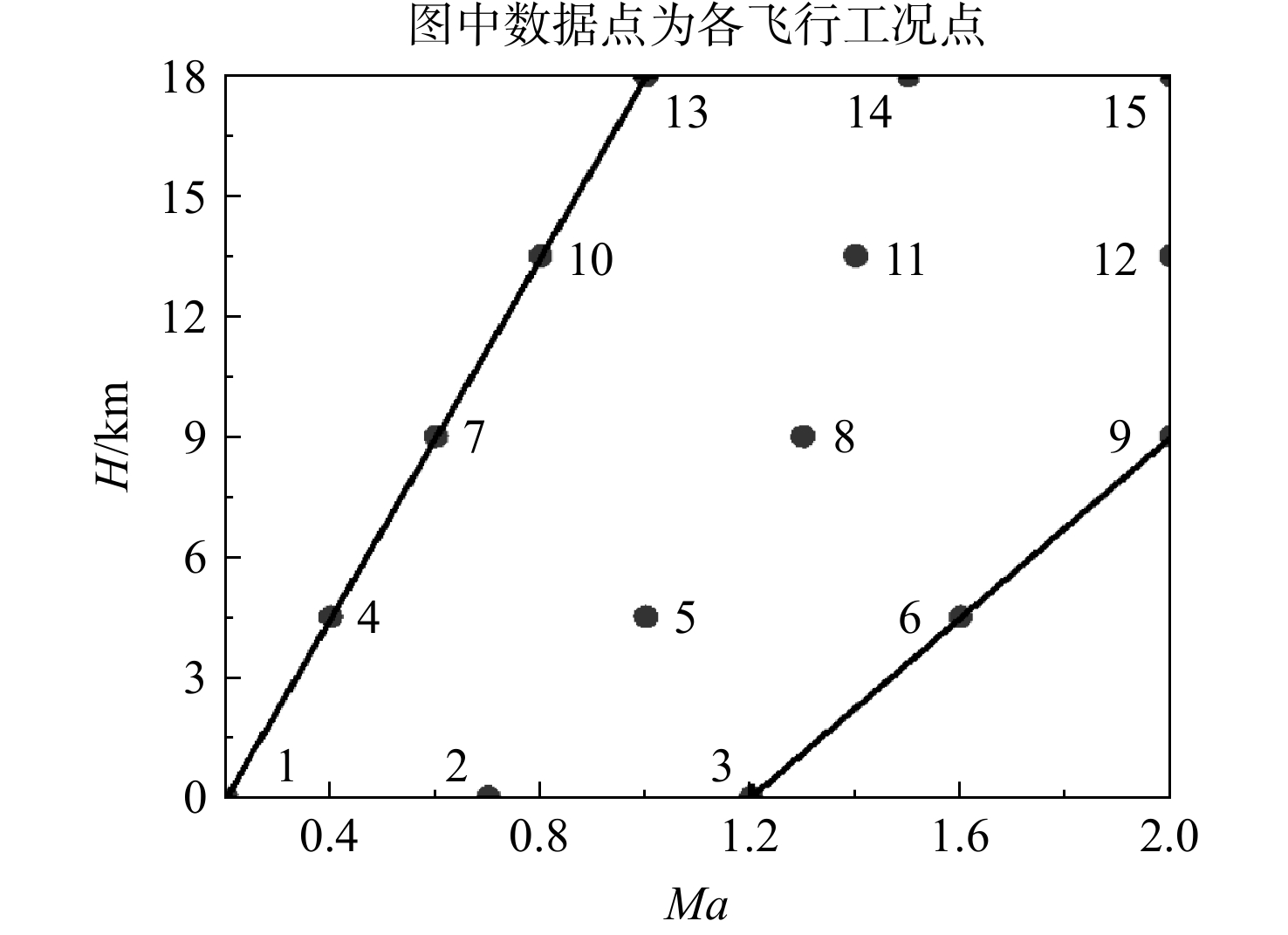
表 6 飞行任务信息
Table 6. Flight mission information
工况编号 任务段 任务描述 1 起飞 S=500 m,H=0 m,Ma=0.2,加力 2 爬升 H=0~10150 m,Ma =0.83 3 巡航 H=10150~11308 m,
Ma=0.83~0.864 下降 Ma=0.65 5 加速 Ma=0.45~0.85,t=60 s 6 空战 Ma=0.85 7 爬升 Ma=0.87 8 巡航 H=13320~13716 m,Ma=0.87 9、10 下降着陆 飞行高度从13716 m下降至
水平面着陆状态,Ma=0.611 最大马赫数 H=9000~18000 m,Ma=2.0,加力 12 实用升限 H=18000 m,Ma=1.0~2.0,加力 13 最大爬升率 dH/dt=314.5 m/s,H=0 m,Ma=0.8,加力 14 战斗盘旋 H=10000 m,Ma=1.6,加力
下载: 导出CSV
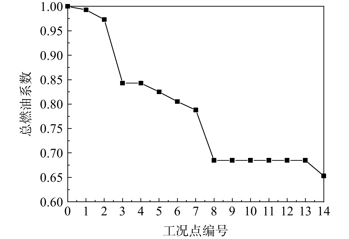
表 7 任务燃油系数计算公式
Table 7. Calculation formula of fuel proportional coefficient
任务段 任务燃油系数 Mff 起飞 0.992~0.995 爬升 1.0065−0.0325Ma 巡航 ${ {\text{e} }^{ - \frac{ {R \cdot r_{ {\rm{SFC} } } \cdot g} }{ { {V_0}\left( {L/D} \right)} } } }$ 空中巡逻 0.9675 空战 $1-{T}_{\text{av} }\cdot r_{ {\rm{SFC} } }\cdot {t}_{ {\rm{CBT} } }/ {W}_{i-1}$ 加速冲刺 0.9795 最短时间爬升 0.997 亚声速巡航爬升 ${ {\text{e} }^{ - \frac{ {R \cdot r_{ {\rm{SFC} } } \cdot g} }{ { {V_0}\left( {L/D} \right)} } } }$ 待机 0.9677 下降着陆 1
下载: 导出CSV
表 8 各工况点需求推力
Table 8. Required thrust under various conditions point
工况点编号 推力/kN 工况点编号 推力/kN 1 122.66 8 12.36 2 51.48 9 1.62 3 14.41 10 2.62 4 1.77 11 55.47 5 41.57 12 20.56 6 44.44 13 135.14 7 24.53 14 65.96
下载: 导出CSV
表 9 发动机设计点参数
Table 9. Parameters of the engine design point
参数 数值 总压比 32 涵道比 0.4 进气流量/(kg/s) 112.4 涡轮前温度/K 1672
下载: 导出CSV
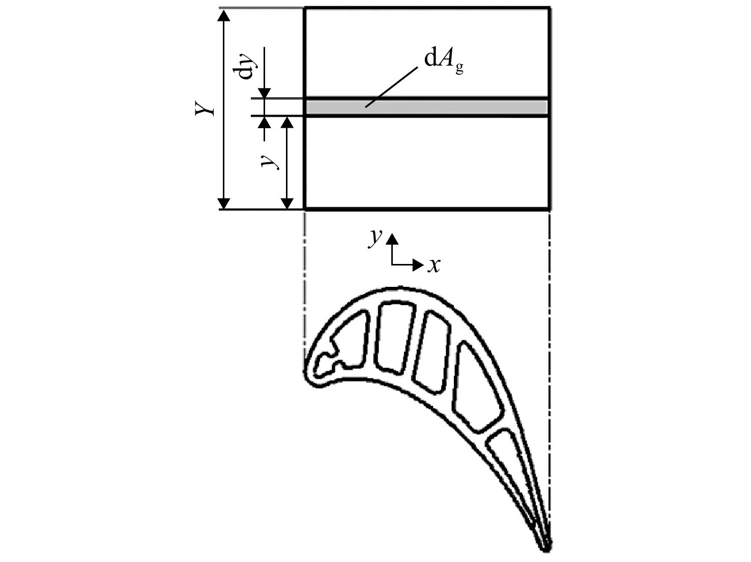
表 10 温度评估模型输入参数
Table 10. Temperature evaluation model input parameters
参数 数值及说明 T0c,i/K 程序计算 mcl/(kg/s) 程序计算 T0g/K 程序计算 λTBC/(W/(m·K)) 1.02 Acl/m2 0.005262 Ag/m2 0.0038115 Y/m 0.0465 λm/(W/(m·K)) 35 W Bim 0.15 BiTBC 0.3 wfc 0.6 εf 0.2(y≤0.1Y) 0.5(y≤0.9Y) 0.1(y>0.9Y)
下载: 导出CSV
表 11 模型输入参数
Table 11. Model input parameters
方案 mcl/(kg/s) εf T0c,i/K 基准方案 5.3 0.5 783 改变冷气量 方案1 5.83 0.5 783 方案2 4.77 0.5 783 改变气膜冷效 方案3 5.3 0.55 783 方案4 5.3 0.45 783 方案5 5.3 0 783 改变冷气温度 方案6 5.3 0.5 705 方案7 5.3 0.5 861
下载: 导出CSV
-
[1] 卫海洋,徐敏,刘晓曦. 涡轮叶片冷却技术的发展及关键技术[J]. 飞航导弹,2012(2): 61-64. doi: 10.16338/j.issn.1009-1319.2012.02.007WEI Haiyang,XU Min,LIU Xiaoxi. Development and key technologies of turbine blade cooling technology[J]. Aerodynamic Missile Journal,2012(2): 61-64. (in Chinese) doi: 10.16338/j.issn.1009-1319.2012.02.007 [2] 赵利峰. 涡轮叶片冷却技术[EB/OL]. [2020-09-01]. https: //wenku.baidu.com/view/9c54a87a87c24028905fc317.html. [3] HALLS G A. Air cooling of turbine blades and vanes: an account of the history and development of gas turbine cooling[J]. Aircraft Engineering and Aerospace Technology,1967,39(8): 4-14. [4] AINLEY D G. Internal air cooling for turbine blades: a general design survey[R]. Aeronautical Research Council Reports and Memorandum 3013, 1957. [5] HOLLAND M J,THAKE T F. Rotor blade cooling in high pressure turbines[J]. Journal of Aircraft,1980,17(6): 412-418. doi: 10.2514/3.44668 [6] TORBIDONI L,HORLOCK J H. A new method to calculate the coolant requirements of a high temperature gas turbine blade[J]. Journal of Turbomachinery,2005,127(1): 191-199. doi: 10.1115/1.1811100 [7] WILCOCK R C,YOUNG J B,HORLOCK J H. The effect of turbine blade cooling on the cycle efficiency of gas turbine power plants[J]. Journal of Engineering for Gas Turbines and Power,2005,127(6): 109-120. [8] CONSONNI S. Performance prediction of gas/steam cycles for power generation[D]. Princeton, US: Princeton University, 1992. [9] 刘尚明,魏成亮,蒲星星,等. 一种计算燃气轮机透平叶片温度分布和冷却空气需求量的修正的解析模型[J]. 中国电机工程学报,2012,32(14): 88-94. doi: 10.13334/j.0258-8013.pcsee.2012.14.014LIU Shangming,WEI Chengliang,PU Xingxing,et al. A modified analytical model for calculating gas turbine blade temperature distribution and cooling air demand[J]. Proceedings of the CSEE,2012,32(14): 88-94. (in Chinese) doi: 10.13334/j.0258-8013.pcsee.2012.14.014 [10] 郑玺龙. 基于战斗机飞行任务的涡扇发动机参数设计研究[D]. 南京: 南京航空航天大学, 2018.ZHENG Xilong. Research of turbofan parameter design based on fighter flight missions [D]. Nanjing: Nanjing University of Aeronautics and Astronautics, 2018. (in Chinese) [11] 陈仲光,张志舒,李德旺,等. F119发动机总体性能特点分析与评估[J]. 航空科学技术,2013(3): 43-46. doi: 10.3969/j.issn.1007-5453.2013.03.013CHEN Zhongguang,ZHANG Zhishu,LI Dewang,et al. Analysis and evaluation of overall performance characteristics of F119 engine[J]. Aeronautical Science and Technology,2013(3): 43-46. (in Chinese) doi: 10.3969/j.issn.1007-5453.2013.03.013 [12] CHIESA P,MACCHI E. A thermodynamic analysis of different options to break 60% electric efficiency in combined cycle power plants[J]. Journal of Engineering for Gas Turbines and Power,2004,126(4): 770-785. doi: 10.1115/1.1771684 [13] 杨世铭, 陶文铨. 传热学[M]. 4版. 北京: 高等教育出版社, 2006. [14] ALY W I A. Numerical study on turbulent heat transfer and pressure drop of nanofluid in coiled tube-in-tube heat exchangers[J]. Energy Conversion and Management,2014,79: 304-316. doi: 10.1016/j.enconman.2013.12.031 [15] DE WOLF W B, WOLDENDORP S, TINGA T. Analysis of combined convective and film cooling on an existing turbine blade[R]. National Aerospace Laboratory, NLR Technical Publication TP 2001-148, 2001. [16] LALLINI V,JANIKOVIC J,PILIDISP,et al. A calculation tool of a turbine cooling air schedule for general gas turbine simulation algorithms[J]. Journal of Turbomachinery,2012,134(4): 041003.1-041003.8. [17] 邓丽君,宣文韬,钟博,等. 涡轮叶片表面温度场及综合冷却效果试验研究[J]. 南京航空航天大学学报,2021,53(3): 442-448. doi: 10.16356/j.1005-2615.2021.03.016DENG Lijun,XUAN Wentao,ZHONG Bo,et al. Experimental research on surface temperature field and comprehensive cooling effect of turbine blade[J]. Journal of Nanjing University of Aeronautics and Astronautics,2021,53(3): 442-448. (in Chinese) doi: 10.16356/j.1005-2615.2021.03.016 [18] MATTINGLY J D, HEISER W H, PRATT D T. Aircraft engine design second edition[M]. Reston, US: American Institute of Aeronautics and Astronautics, 2002. [19] Lockheed Martin Corporation. F-16C/D supplemental flight manual T. O. GR1F-16CJ-1-1[M]. Bethesda, US: Lockheed Martin Corporation, 2003. [20] 沙正平. 飞机设计手册: 第4册 军用飞机总体设计[M]. 北京: 航空工业出版社, 2005. [21] 中国航发四川燃气涡轮研究院. F100-PW-229涡扇发动机简介[J]. 燃气涡轮试验与研究,2000,13(4): 41-62.Sichuan Gas Turbine Research Establishment,Aero Engine Corporation of China (AECC). Introduction to F100-PW-229 turbofan engine[J]. Gas Turbine Experiment and Research,2000,13(4): 41-62. (in Chinese) -


 点击查看大图

计量
- 文章访问数: 179
- HTML浏览量: 137
- PDF量: 86
- 被引次数: 0