






Performance of swirling-flow single trapped vortex combustor under different swirler schemes
-
摘要:
为研究旋流驻涡燃烧室的燃烧性能,设计了3种旋流器方案(基准型、小流通面积和外加套筒),在进口温度493 K、常压条件下,采用RP-3航空煤油作为燃料,凹腔当量比在0.8~1.8之间,开展了热态试验。结果表明:基准型和小流通面积的主燃区火焰为脱体火焰,而外加套筒则为V型驻定火焰,且小流通面积和加套筒的主燃区火焰更加集中。燃烧效率方面,基准型最低,而小流通面积最高,试验中获得的最高燃烧效率为96.3%。随着凹腔当量比的增加,基准型的燃烧效率不断增加,而小流通面积的则先基本不变,随后略有增加,外加套筒的则先快速增加,然后缓慢增加。此外,小流通面积的冷态总压损失高于基准型,在进口马赫数为0.31时,两者的冷态总压损失分别为7.2%和4.5%。
Abstract:To investigate the combustion performance of swirling-flow single trapped vortex combustor, three swirler schemes (baseline type, small flow area and additional flare) were designed and thermal tests were carried out at an inlet temperature of 493 K and at atmospheric pressure, using RP-3 aviation kerosene as fuel and a cavity equivalent ratio between 0.8 and 1.8. Results showed that the flame in the main combustion zone of the baseline and small flow area schemes was a deconfined flame, while that of the plus flare scheme was a V-shaped standing flame, and the flame in the main combustion zone of the small flow area and plus flare schemes was more concentrated. In terms of combustion efficiency, the base type scheme was the lowest while the small flow area scheme was the highest, and the highest combustion efficiency obtained in the test was 96.3%. The combustion efficiency of the baseline model increased with the increase of the cavity equivalent ratio, while that of the small flow area solution remained basically the same at first and then increased slightly, and that of the plus flare solution increased rapidly and then slowly. The total pressure loss of the small circulation area scheme was higher than that of the baseline type, which was 7.2% and 4.5% respectively, at an inlet Mach number of 0.31.
-
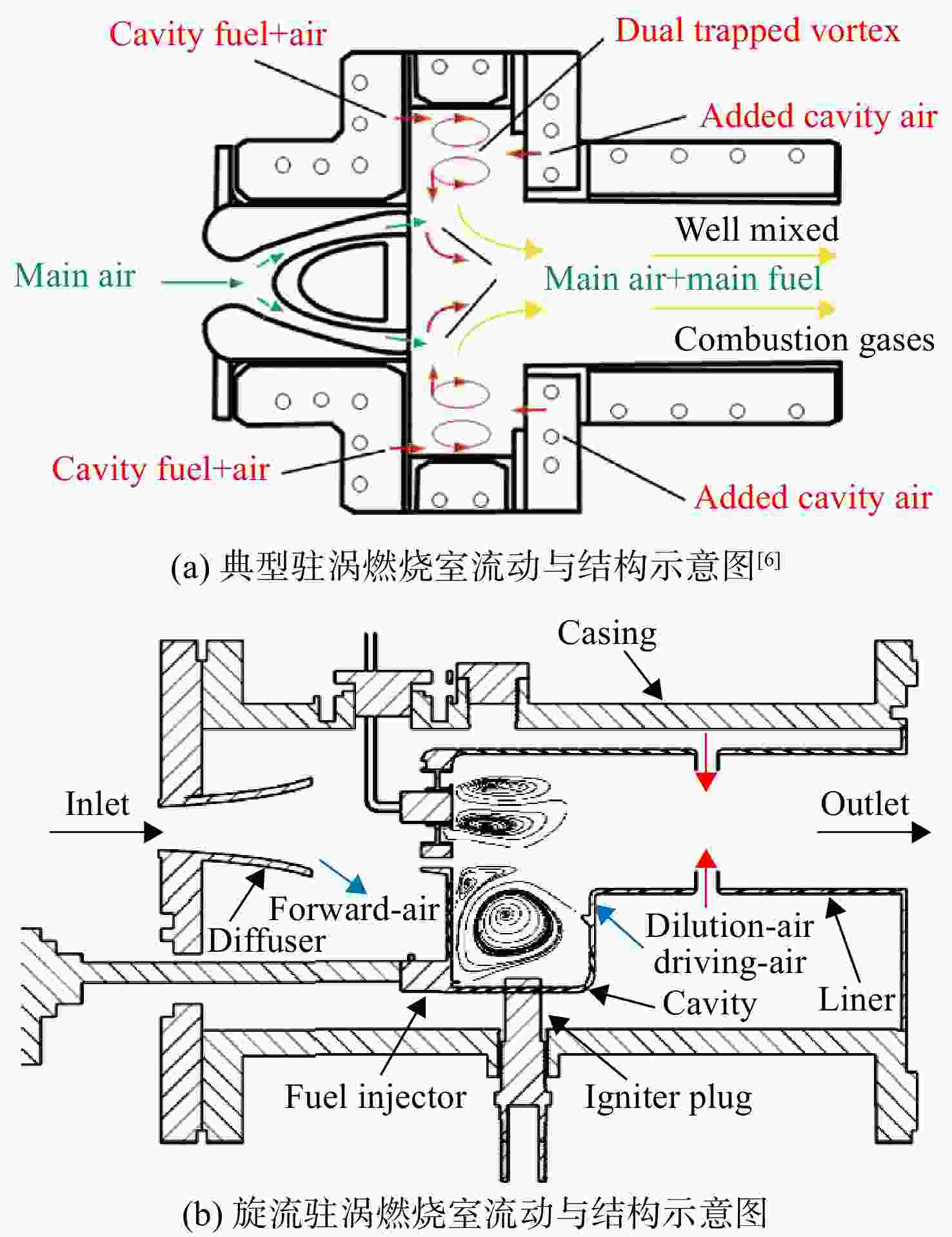
图 1 典型驻涡燃烧室与旋流驻涡燃烧室结构示意图
Figure 1. Schematic diagram of generic TVC and swirling-flow single TVC

图 3 试验系统示意图
1 空气压缩机;2放气阀门;3进气阀门;4孔板流量计;5电加温器;6进气测试段;7试验段;8排气测试段;9排气段;10测试系统;11油库;12燃油阀;13燃油泵;14压力表。
Figure 3. Schematic diagram of experimental system
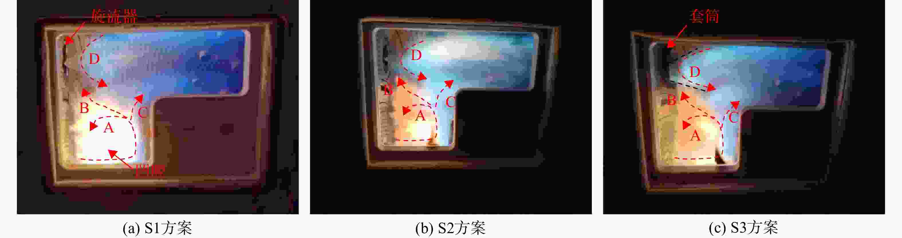
图 7 Tin = 493 K、 Main = 0.31、
${{\varPhi }_{{\text{ca}}}}$ = 1.2时不同旋流器结构方案下火焰形态Figure 7. Flame form of different swirler structure schemes at Tin = 493 K, Main = 0.31,
${{\varPhi }_{{\text{ca}}}}$ = 1.2
图 8 Tin = 493 K、Main = 0.31时不同旋流器结构方案下冷态流场(数值模拟)
Figure 8. Flow field of different swirler structure schemes at Tin = 493 K, Main = 0.31 (numerical simulation)
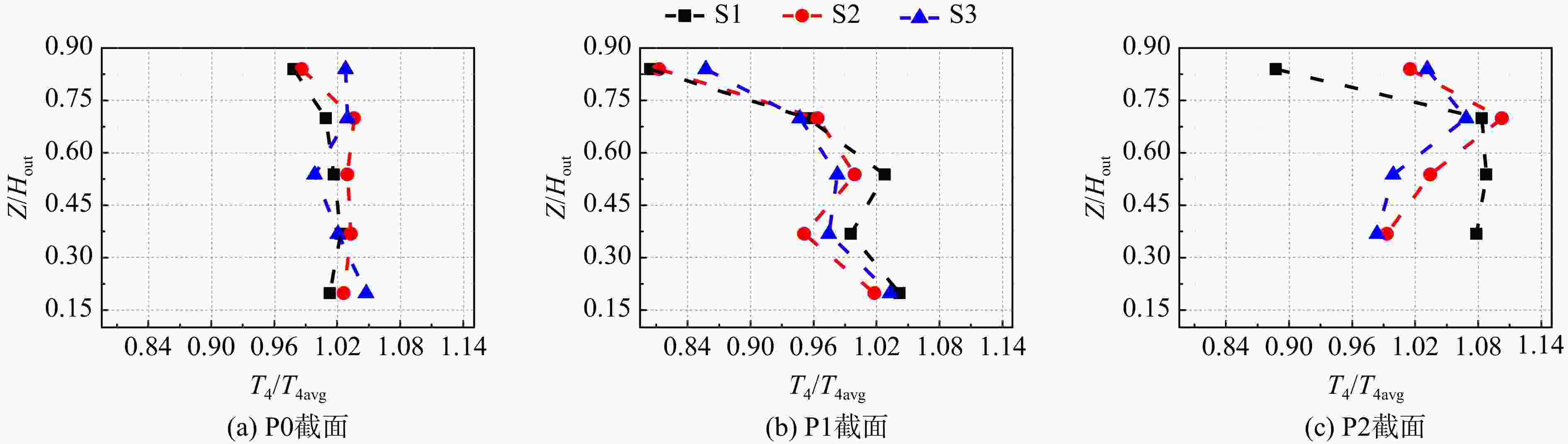
图 9 Tin = 493 K、Main = 0.31、
${{\varPhi }_{{\text{ca}}}}$ = 1.2时出口无量纲温度分布Figure 9. Radial outlet dimensionless temperature distributions at Tin = 493 K , Main = 0.31,
${{\varPhi }_{{\text{ca}}}}$ = 1.2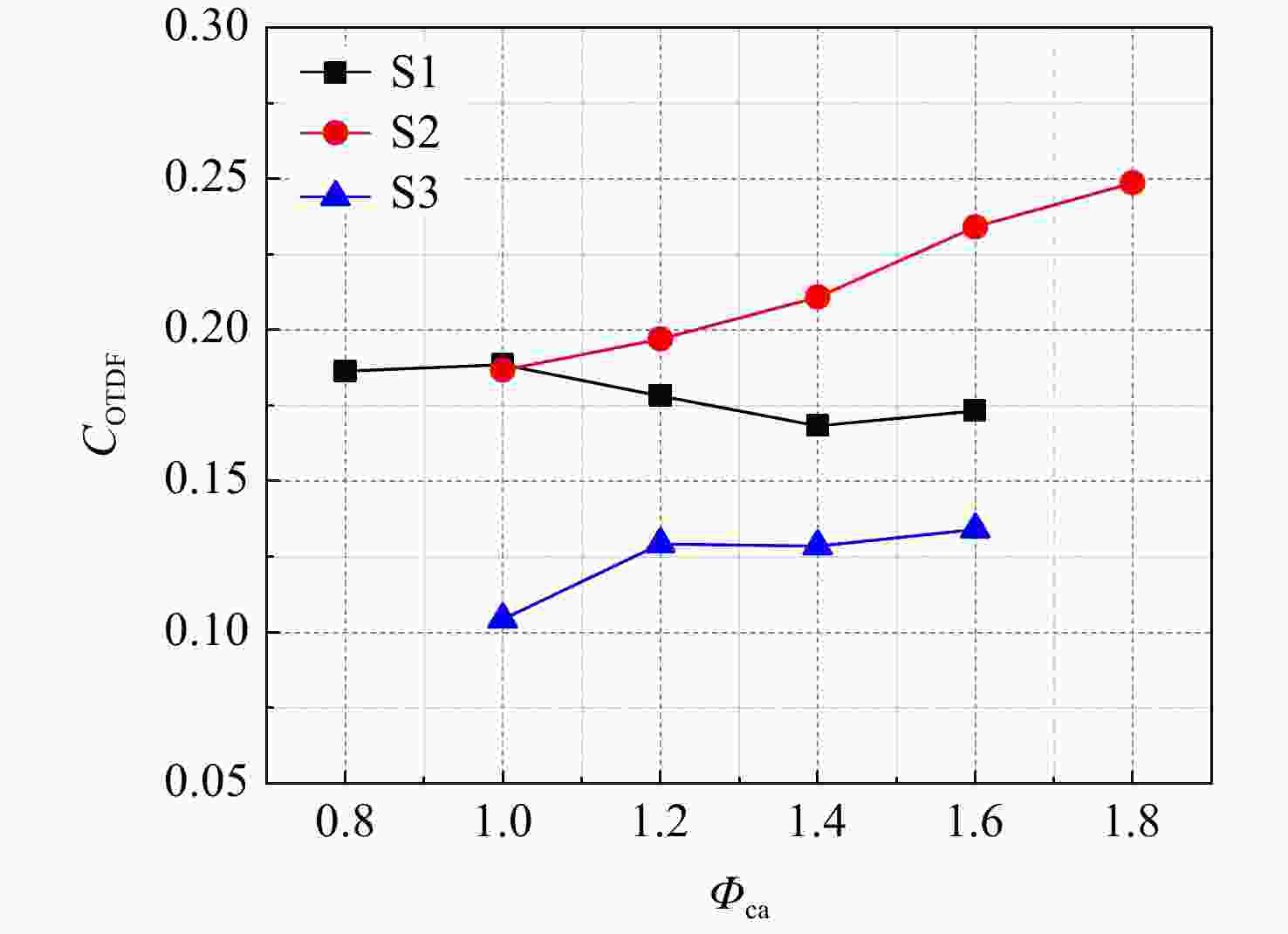
图 10 Tin = 493 K、pin = 102 kPa、 Main = 0.31时出口COTDF分布
Figure 10. COTDF distributions at Tin = 493 K, pin = 102 kPa, Main = 0.31
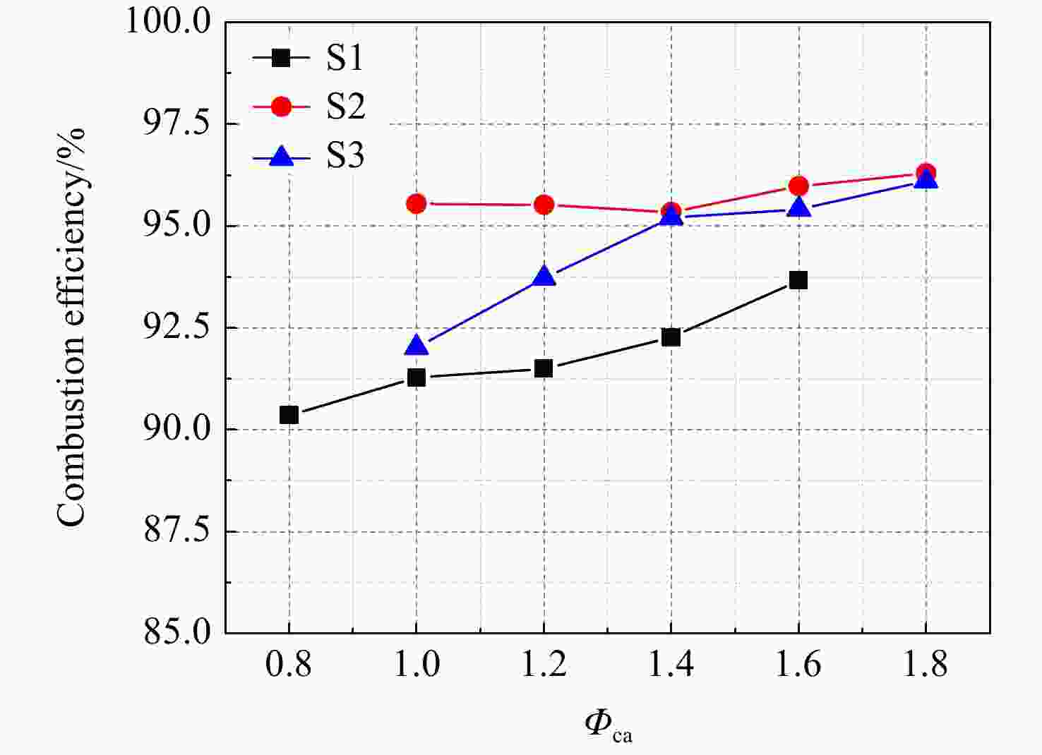
图 11 不同旋流器结构方案下燃烧效率随凹腔当量比变化(pin = 102 kPa、Tin = 493 K、Main = 0.31、RFAR = 0.0177)
Figure 11. Combustion efficiency varying with cavity equivalence ratio of different swirler structure schemes(pin = 102 kPa,Tin = 493 K,Main = 0.31,RFAR = 0.0177)
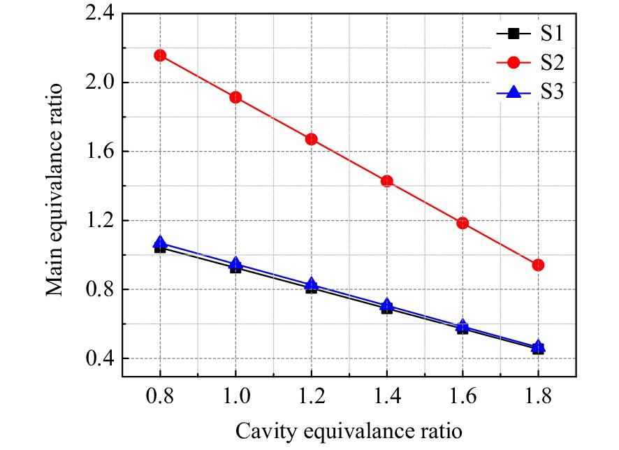
图 12 不同旋流器结构方案下主燃区当量比随凹腔当量比变化(pin = 102 kPa、Tin = 493 K、Main = 0.31、RFAR = 0.0177)
Figure 12. Main equivalence ratio varying with cavity equivalence ratio of different swirler structure schemes(pin = 102 kPa,Tin = 493 K,Main = 0.31,RFAR = 0.0177)
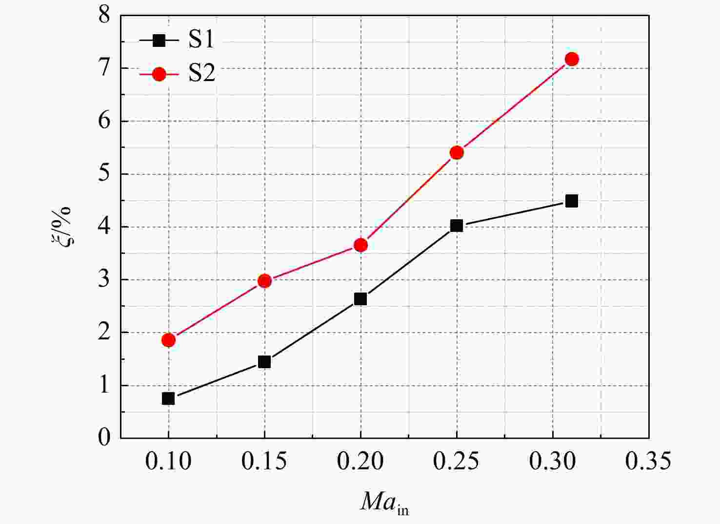
图 13 不同旋流器结构方案下冷态总压损失随进口马赫数变化(Tin = 300 K、pin = 102 kPa)
Figure 13. Total pressure loss varying with combustor inlet Mach number of different swirler structure schemes (Tin = 300 K,pin = 102 kPa)
表 1 旋流器结构方案
Table 1. Schemes of swirler structure
旋流器方案 套筒 流通面积/% 旋流数Sn S1 无 100 0.791 S2 无 40 0.865 S3 有 100 0.791  下载: 导出CSV
表 2 旋流驻涡燃烧室流量分配
Table 2. Flow distribution of swirling-flow single TVC
进气位置 分配比例/% S1方案 S2方案 S3方案 凹腔前壁进气 6.8 7.4 6.7 凹腔后壁进气 7.4 8.4 6.9 旋流器进气 13.9 5.2 13.5 掺混孔进气 32.6 35.9 32.2
下载: 导出CSV
表 3 旋流驻涡燃烧室试验工况
Table 3. Test condition for swirling-flow single TVC
参数 数值 进口温度Tin/K 493.0 空气流量$ {\dot{m}}_{\mathrm{a}} $/(kg/s) 0.33 进口马赫数Main 0.31 总油气比RFAR 0.0177 凹腔当量比${ {\varPhi }_{ {\text{ca} } } }$ 0.8~1.8 凹腔燃油占比/% 31~69
下载: 导出CSV
表 4 试验测量误差
Table 4. Error of measurement parameters
参数 测试装置/计算方法 数值 误差/% 进口温度Tin/K K型热电偶 493 0.40 进口空气压力pin/kPa 压力表 102 0.40 空气流量${\dot{m} }_{\mathrm{a} }{\rm{/} } ({\rm{kg/s} }) $ 孔板流量计 0.33 0.57 进口马赫数Main ${M{a} }_{\rm{i}\rm{n} }=\dfrac{ {\dot{m} }_{\mathrm{a} } }{\rho A{ (\gamma R{T}_{i}) }^{\tfrac{1}{2} } }$ 0.31 0.57 凹腔当量比${ {\varPhi }_{ {\text{ca} } } }$ Φca = fca/fa,st 0.8~1.8 0.7 出口无量纲温度$ ({T_4}/{T_{{\text{4ave}}}}) $ B型热电偶 0.80~1.12 0.7 $\varphi ( { {\text{CO} } } ) $/10−6 700NDIR CO/CO2/O2分析仪 1538.3~3118.4 0.1 $\varphi ( { {\text{C} }{ {\text{O} }_{\text{2} } } } ) $/% 700NDIR CO/CO2/O2分析仪 3.19~3.52 0.1 $\varphi ({ { {\text{O} }_{\text{2} } } } ) $/% 700NDIR CO/CO2/O2分析仪 16.14~20.9 0.1 $\varphi ({ {\text{UHC} } } ) $/10−6 700HFID总碳氢分析仪 708.1~1421.2 0.3 燃烧效率ƞb/% ${\eta }_{\rm{b} }=\dfrac{\varphi (\text{C}{\text{O} }_{2}) +0.531\varphi (\text{CO}) -0.319\varphi (\text{C}{\text{H} }_{4}) -0.397\varphi ({\mathrm{H} }_{2})}{\varphi (\text{C}{\text{O} }_{2}) +\varphi (\text{C}{\text{O} }_{2}) +\varphi (\text{UHC})}$ 90.4~ 96.3 0.33
下载: 导出CSV
-
[1] HSU K Y,GOSS L P,ROQUEMORE W M. Characteristics of a trapped-vortex combustor[J]. Journal of Propulsion and Power,1998,14(1): 57-65. doi: 10.2514/2.5266 [2] MEYER T R, BROWN M S, FONOV S, et al. Optical diagnostics and numerical characterization of a trapped-vortex combustor[R]. AIAA-2002-3863, 2002. [3] HSU K Y, GOSS L P, TRUMP D D. Performance of a trapped-vortex combustor[R]. AIAA-1995-0810, 1995. [4] ROQUEMORE W M, SHOUSE D, BURRUS D, et al. Trapped vortex combustor concept for gas turbine engines[R].Reno, US: the 39th Aerospace Sciences Meeting and Exhibit, 2001. [5] BURRUS D L, JOHNSON A W, ROQUEMORE W M, et al. Performance assessment of a prototype trapped vortex combustor concept for gas turbine application[R]. ASME Paper 2001-GT-0087, 2001. [6] HENDRICKS R C, SHOUSE D T, ROQUEMORE W M, et al. Experimental and computational study of trapped vortex combustor sector rig with tri-pass diffuser[R]. NASA/TM-2004-212507, 2004. [7] BRANKOVIC A, RYDER R C, HENDRICKS R C, et al. Emissions prediction and measurement for liquid- fueled TVC combustor with and without water injection[R]. NASA/TM-2005-213441, 2005. [8] 金义. 高油气比驻涡燃烧室流动与燃烧性能研究[D]. 南京: 南京航空航天大学, 2013.JIN Yi. An investigation on the flow and combustion characteristics of a high fuel air ratio trapped-vortex combustor[D]. Nanjing: Nanjing University of Aeronautics and Astronautics, 2013. (in Chinese) [9] LI M Y,HE X M,ZHAO Y L,et al. Dome structure effects on combustion performance of a trapped vortex combustor[J]. Applied Energy,2017,208: 72-82. doi: 10.1016/j.apenergy.2017.10.029 [10] 方杰. 气动多点供油系统性能研究[D]. 南京: 南京航空航天大学, 2013.FANG Jie. An investigation on the performance of aerodynamic multi-point fuel injector[D]. Nanjing: Nanjing University of Aeronautics and Astronautics, 2013. (in Chinese) [11] MEHTA J M, SHIN H W, WISLER D C. Mean velocity and turbulent flow-field characteristics inside an advanced combustor swirl cup[R]. Reno, US: AIAA Aerospace Sciences Meeting, 2013. [12] WANG H Y,MCDONELL V G,SOWA W A,et al. Scaling of the two-phase flow downstream of a gas turbine combustor swirl cup: mean quantities[J]. Journal of Engineering for Gas Turbines and Power,1992,115(3): 1-4. [13] 曾卓雄,张龙. 单旋流驻涡燃烧室流场结构的数值模拟[J]. 推进技术,2017,38(4): 896-902. doi: 10.13675/j.cnki.tjjs.2017.04.021ZENG Zhuoxiong,ZHANG Long. Numerical simulation on single swirl trapped vortex combustor flow[J]. Journal of Propulsion Technology,2017,38(4): 896-902. (in Chinese) doi: 10.13675/j.cnki.tjjs.2017.04.021 [14] 曾卓雄,薛锋,张龙. 双旋流驻涡燃烧室湍流燃烧流动的数值分析[J]. 推进技术,2017,38(7): 1572-1578. doi: 10.13675/j.cnki.tjjs.2017.07.017ZENG Zhuoxiong,XUE Feng,ZHANG Long. Numerical simulation of turbulence flow in a dual swirl trapped vortex combustor[J]. Journal of Propulsion Technology,2017,38(7): 1572-1578. (in Chinese) doi: 10.13675/j.cnki.tjjs.2017.07.017 [15] 姜磊,熊健,肖波,等. 旋流杯结构及进气参数对燃烧性能的影响[J]. 推进技术,2020,41(3): 605-614. doi: 10.13675/j.cnki.tjjs.190199JIANG Lei,XIONG Jian,XIAO Bo,et al. Effects of swirl cup structure and inlet parameters on combustion characteristics[J]. Journal of Propulsion Technology,2020,41(3): 605-614. (in Chinese) doi: 10.13675/j.cnki.tjjs.190199 [16] 莫妲,程明,张成凯,等. 三旋流器加装外套环对燃烧性能的影响[J]. 航空动力学报,2016,31(7): 1569-1574.MO Da,CHENG Ming,ZHANG Chengkai,et al. Effect of triple swirler with an outer ring on combustion performance[J]. Journal of Aerospace Power,2016,31(7): 1569-1574. (in Chinese) [17] ZHOU L X. Comparison of studies on flow and flame structures in different swirl combustors[J]. Aerospace Science and Technology,2018,80: 29-37. doi: 10.1016/j.ast.2018.06.032 [18] 彭云晖,林宇震,许全宏,等. 双旋流空气雾化喷嘴喷雾、流动和燃烧性能[J]. 航空学报,2008,29(1): 1-14. doi: 10.3321/j.issn:1000-6893.2008.01.001PENG Yunhui,LIN Yuzhen,XU Quanhong,et al. Atomization, aerodynamics and combustion performance of swirl cup[J]. Acta Aeronautica et Astronautica Sinica,2008,29(1): 1-14. (in Chinese) doi: 10.3321/j.issn:1000-6893.2008.01.001 [19] LEFEBVRE A H, BALLAL D R, BAHR D W. Gas turbine combustion: alternative fuels and emissions[M]. Boca Raton, US: CRC Press, 2010: 142-144. [20] ARCHER S, GUPTA A K. Flow dynamics of unconfined and confined swirl stabilized gaseous flames[R]. Baltimore, US: ASME Power Conference, 2004. [21] NOGENMYR K J,FUREBY C,BAI X S,et al. Large eddy simulation and laser diagnostic studies on a low swirl stratified premixed flame[J]. Combustion and Flame,2009,156(1): 25-36. doi: 10.1016/j.combustflame.2008.06.014 [22] NOGENMYR K J,CAO H J,CHAN C K,et al. Effects of confinement on premixed turbulent swirling flames using large eddy simulation[J]. Combustion Theory and Modelling,2013,17(6): 1003-1019. doi: 10.1080/13647830.2013.820842 [23] 王明瑞,肖阳,韩冰,等. 航空燃气涡轮发动机燃气分析测试及计算方法[J]. 航空动力学报,2015,30(11): 2568-2574. doi: 10.13224/j.cnki.jasp.2015.11.002WANG Mingrui,XIAO Yang,HAN Bing,et al. Gas analysis test and calculation method of aeroengine[J]. Journal of Aerospace Power,2015,30(11): 2568-2574. (in Chinese) doi: 10.13224/j.cnki.jasp.2015.11.002 -


 点击查看大图

计量
- 文章访问数: 831
- HTML浏览量: 706
- PDF量: 330
- 被引次数: 0