


Analysis of flow entropy generation in aero-engine grate and construction of low entropy generation grate
-
摘要:
建立篦齿熵产分析的数值模拟方法并经试验验证方法的准确性,进而揭示了台阶式篦齿的倾角、齿顶宽度、齿高、台阶高度变化下的流动熵产机理及导致熵产的主要流动特征。在此基础上最终从系统熵产视角对篦齿进行优化和特性分析。结果表明:篦齿齿顶区域相对耗散强度较大,导致该区域存在的齿顶涡具有较强增阻作用,对于提升篦齿局部熵产,降低系统熵产有重要作用。通过主动构造齿顶涡(增阻涡)可以实现增强篦齿局部熵产、减小泄漏量的设计目标。优化后的台阶式篦齿结构较初始台阶齿的封严性能提升24%。
Abstract:The numerical simulation method of grate entropy generation analysis was established, and the accuracy of the method was verified by tests. Then, the flow entropy generation mechanism and the main flow characteristics leading to entropy generation under the changes of inclination angle, tooth top width, tooth height and step height of stepped grate were revealed. On this basis, the grate was optimized and analyzed from the perspective of system entropy generation. The results showed that the relative dissipation intensity in the top region of the grate was large, resulting in strong drag increasing effect of the top vortex in this region, and contributing a lot to improving the local entropy generation of the grate and reducing the system entropy generation. The design goal of enhancing the local entropy generation of the grate and reducing the leakage can be achieved by actively constructing the tooth top vortex (drag increasing vortex); the sealing performance of the optimized stepped grate structure was 24% higher than that of the initial stepped teeth.
-
Key words:
- grate /
- entropy generation /
- drag increasing vortex /
- configuration /
- sealing performance
-

图 1 CFM56-7发动机涡轮盘腔空气系统封严结构局部示意图
Figure 1. Partial schematic diagram of sealing structure of CFM56-7 engine turbine disk cavity air system

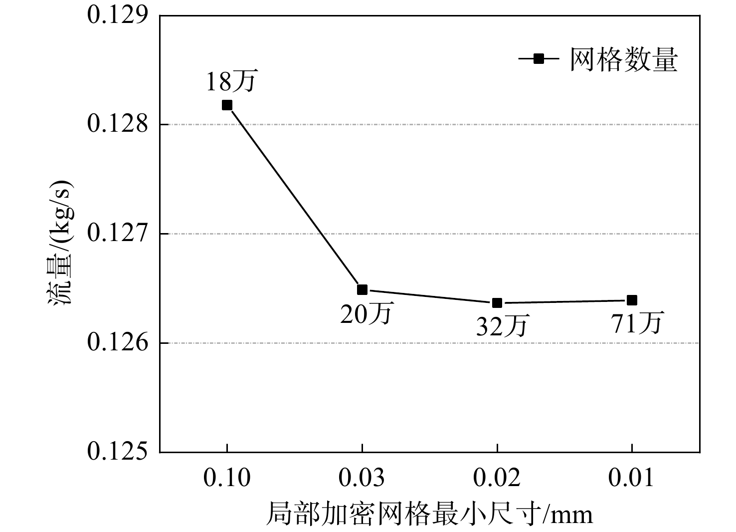
图 4 局加密网格最小尺寸无关性计算
Figure 4. Calculation of minimum size independence of local refined mesh

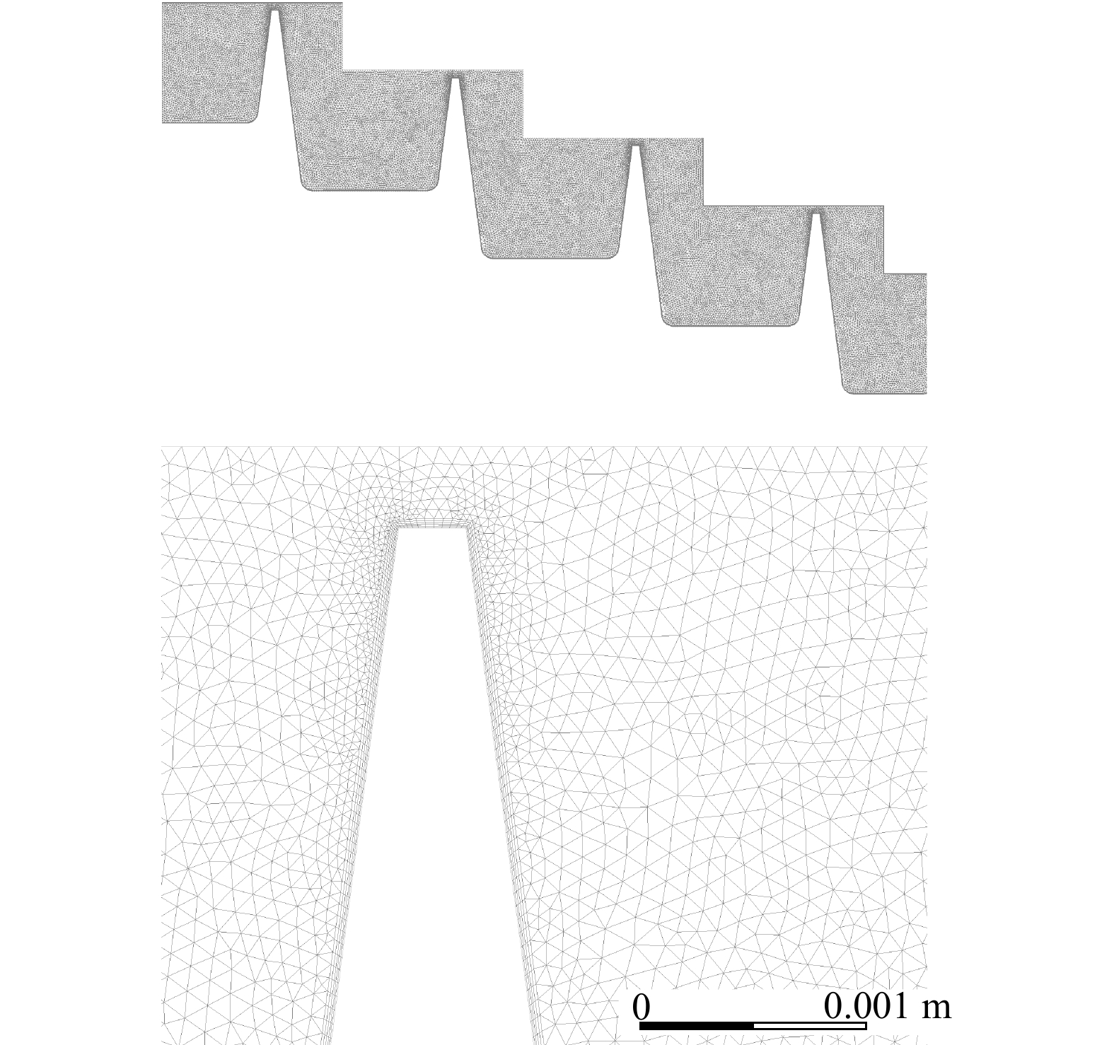
图 5 网格划分及附面层网格、齿尖网格局部加密
Figure 5. Mesh generation and local densification of boundary layer mesh and tooth tip mesh

图 8 验证性试验结果与数值计算结果比对
Figure 8. Comparison between confirmatory test results and numerical calculation results

图 11 篦齿倾角变化齿顶局部熵产分布图
Figure 11. Distribution diagram of local entropy generation at the tooth top with grate inclination angle change

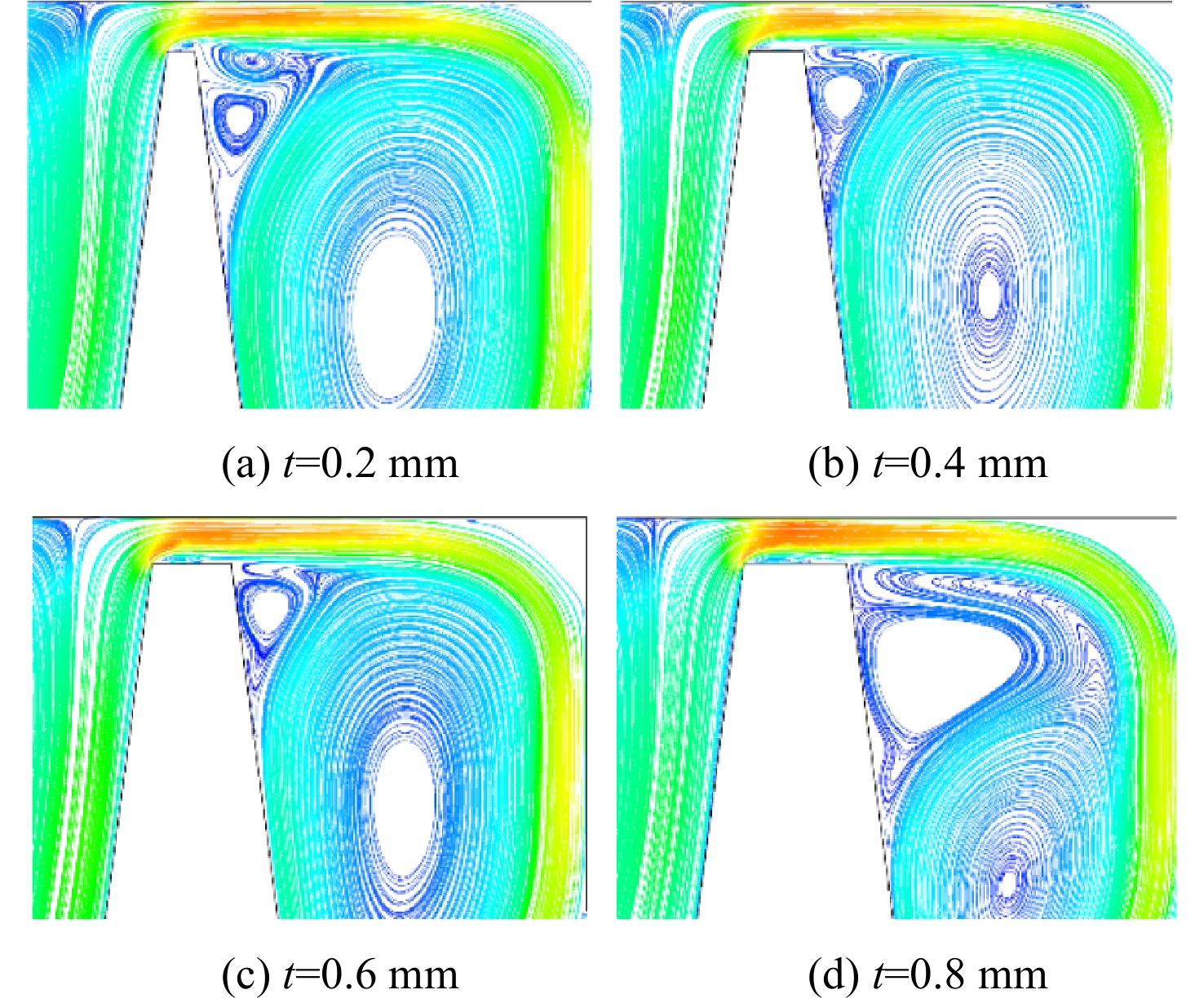
图 13 齿顶宽度变化齿顶局部熵产分布图
Figure 13. Distribution diagram of local entropy generation at tooth top with tooth top width change

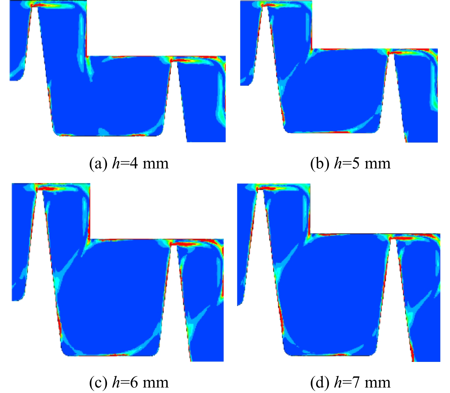
图 15 齿高变化局部熵产分布图
Figure 15. Distribution diagram of local entropy generation withtooth height change

图 17 台阶高度变化局部熵产分布图
Figure 17. Distribution diagram of local entropy generation with step height change

图 22 优化台阶式篦齿熵产分布图
Figure 22. Distribution diagram of entropy generation of optimized stepped grate
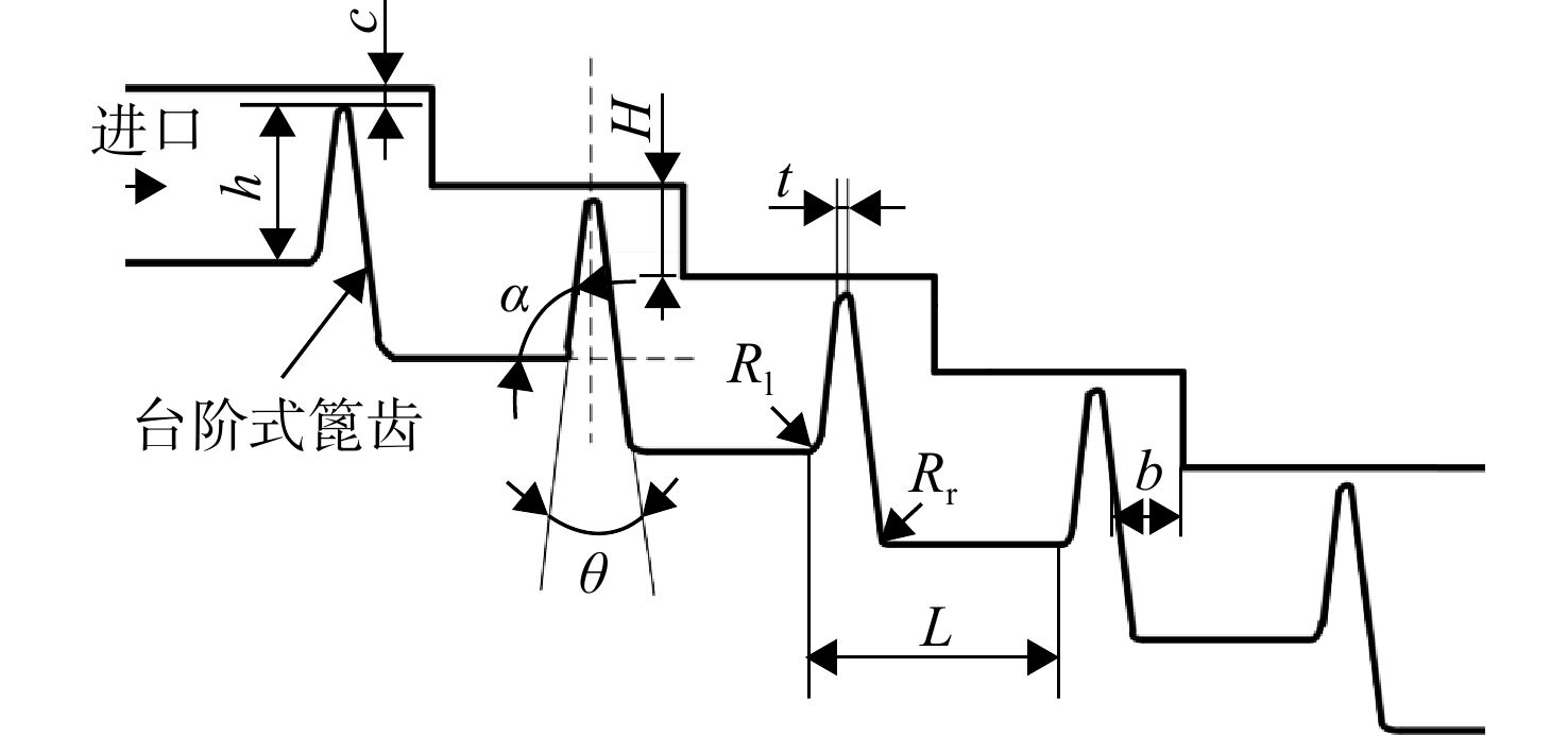
表 1 篦齿几何参数符号及初始值
Table 1. Symbols and initial values of geometric parameters of grate
几何参数 初始值 台阶高度H/mm 3 齿间距L/mm 8 齿高h/mm 5 齿顶宽度t/mm 0.3 篦齿倾角α/(°) 90 篦齿前后侧夹角θ/(°) 15 径向间隙c/mm 0.36 轴向间隙b/mm 3 迎风侧齿根倒圆半径Rl/mm 0.5 背风侧齿根倒圆半径Rr/mm 0.5  下载: 导出CSV
表 2 试验中台阶式篦齿结构几何参数
Table 2. Geometric parameters of stepped grate structure in test bench
几何参数 取值 台阶高度H/mm 3 齿间距L/mm 6 齿高h/mm 6 齿顶宽度t/mm 0.8 篦齿倾角α/(°) 90 篦齿前后侧夹角θ/(°) 16 径向间隙c/mm 0.6 轴向间隙b/mm 2.4 迎风侧齿根倒圆Rl/mm 0.5 背风侧齿根倒圆Rr/mm 0.5
下载: 导出CSV
表 3 优化后台阶式篦齿结构的几何参数取值表
Table 3. Table of geometric parameters for optimized stepped grate structure
几何参数 取值 台阶高度H/mm 1 齿间距L/mm 6 齿高h/mm 4 齿顶宽度t/mm 0.2 篦齿倾角α/(°) 50 篦齿前后侧夹角θ/(°) 15 径向间隙c/mm 0.36 轴向间隙b/mm 3 迎风侧齿根倒圆Rl/mm 0.5 背风侧齿根倒圆Rr/mm 0.5
下载: 导出CSV
-
[1] Federal Aviation Administration, Department of Transportation. Airworthiness standards, aircraft engines: CFR 14 Part 33[S]. Washington DC: Federal Aviation Administration, 2012: 33.1-33.201. [2] BUNKER R S. Gas turbine heat transfer: ten remaining hot gas path challenges[J]. Journal of Turbomachinery,2007,129(2): 193-201. doi: 10.1115/1.2464142 [3] 倪萌,朱惠人,裘云,等. 航空发动机涡轮叶片冷却技术综述[J]. 燃气轮机技术,2005,18(4): 25-33. doi: 10.3969/j.issn.1009-2889.2005.04.006NI Meng,ZHU Huiren,QIU Yun,et al. Overview of the cooling technology of aero-engine turbine blade[J]. Gas Turbine Technology,2005,18(4): 25-33. (in Chinese) doi: 10.3969/j.issn.1009-2889.2005.04.006 [4] RHODE D L,DEMKO J A,TRAEGNER U K,et al. Prediction of incompressible flow in labyrinth seals[J]. Journal of Fluids Engineering,1986,108(1): 19-25. doi: 10.1115/1.3242535 [5] DEMKO J A,MORRISON G L,RHODE D L. Effect of shaft rotation on the incompressible flow in a labyrinth seal[J]. Journal of Propulsion and Power,1990,6(2): 171-176. doi: 10.2514/3.23240 [6] DEMKO J A,MORRISON G L,RHODE D L. The prediction and measurement of incompressible flow in a labyrinth seal[J]. Journal of Engineering for Gas Turbines and Power,1989,111(4): 697-702. doi: 10.1115/1.3240315 [7] RHODE D L,SOBOLIK S R. Simulation of subsonic flow through a generic labyrinth seal[J]. Journal of Engineering for Gas Turbines and Power,1986,108(4): 674-680. doi: 10.1115/1.3239964 [8] RHODE D L,HIBBS R I. New model for flow over open cavities: Part Ⅰ model development[J]. Journal of Propulsion and Power,1992,8(2): 392-297. doi: 10.2514/3.23490 [9] RHODE D L,HIBBS R I. New model for flow over open cavities: Part Ⅱ assessment for seal leakage[J]. Journal of Propulsion and Power,1992,8(2): 398-402. doi: 10.2514/3.23491 [10] RHODE D L,HIBBS R I. Clearance effects on corresponding annular and labyrinth seal flow leakage characteristics[J]. Journal of Tribology,1993,115(4): 699-704. doi: 10.1115/1.2921696 [11] PRASAD B, SETHU MANAVALAN V, NANJUNDA R N. Computational and experimental investigations of straight-through labyrinth seals[R]. ASME Paper 97-GT-326, 1997. [12] DENECKE J, DULLENKOF K, WITTING S. Experimental investigation of the total temperrature increase and swirl development in rotating labyrinth seals[R]. ASME Paper GT-2005-68677, 2005. [13] STOFF H. Incompressible flow in a labyrinth seal[J]. Journal of Fluid Mechanics,1980,100(4): 817-829. doi: 10.1017/S0022112080001437 [14] WILLENBORG K, KIM S, WITTIG S. Effects of Renolds number and pressure ratio on leakage loss and heat transfer in a stepped labyrinth seal[R]. ASME Paper 2001-GT-0123, 2001. [15] MILLWARD J A, EDWARDS M F. Windage heating of air passing through labyrinth seals[J]. Journal of Turbomachinery, 1996, 118(2): 414-419. [16] STOCKER H L, COX D M. Aerodynamic performance of conventional and advanced design labyrinth seals with solid-smooth, abradable, and honeycomb lands[R]. NASA CR-135307, 1977. [17] RHODE D L. Rub-groove width and depth effects on flow predictions for straight-through labyrinth seals[J]. Journal of Tribology,2004,126(4): 781-787. doi: 10.1115/1.1760555 [18] KALI C N, MUSTHAFA T. The effects of tooth tip wear and its axial displacement in rub-grooves on leakage and windage heating of labyrinth seals with honeycomb lands[R]. AIAA-2007-5736, 2007 [19] KUTZ K J , SPEER T M . Simulation of the secondary air system of aero engines[R]. ASME Paper 92-GT-068, 1992. [20] ZHANG M,YANG J,XU Wanjun,et al. Leakage and rotordynamic performance of a mixed labyrinth seal compared with that of a staggered labyrinth seal[J]. Journal of Mechanical Science and Technology,2017,31(5): 2261-2277. doi: 10.1007/s12206-017-0423-7 [21] JIA X,ZHENG Q,JIANG Y,et al. Leakage and rotordynamic performance of T type labyrinth seal[J]. Aerospace Science and Technology,2019,88(5): 22-31. [22] NAYAK K C. Effect of rotation on leakage and windage heating in labyrinth seals with honeycomb lands[J]. Journal of Engineering for Gas Turbines and Power,2020,142(8): 081001.1-081001.11. [23] SUN D, ZHOU M, ZHAO H, et al. Numerical and experimental investigations on windage heating effect of labyrinth seals[J]. Journal of Aerospace Engineering, 2020, 33(5): 4020057.1-4020057.9 . [24] CHARAN N K , DUTTA P. Effect of rub-grooves on leakage and windage heating in straight-through labyrinth seals[J]. Journal of Tribology, 2016, 138(2): 022201.1-022201.11. [25] 杨世铭, 陶文铨. 传热学[M]. 4版. 北京: 高等教育出版社, 2006. [26] DAI Lu. Study on the improvement of resistance characteristics in stepped labyrinth seals[D]. Beijing: Beihang University, 2019 -


 点击查看大图

计量
- 文章访问数: 154
- HTML浏览量: 122
- PDF量: 62
- 被引次数: 0