






Numerical simulation investigation on a hydrogen micromix combustor
-
摘要:
为降低航空发动机和地面燃机碳排放和NOx,提出一种多射流布局的氢燃料微尺度非预混燃烧室头部结构。为获得微尺度非预混燃烧组织机理,以及关键设计参数对燃烧性能的影响,采用
k -ω SST(剪切应力输运)和FGM(火焰面生成流行)方法中的扩散火焰方法,通过9种组分共26步反应开展数值仿真模拟,对动量通量比、当量比、空气和氢气的导流板高度进行敏感性分析,探究氢气与空气的混合特性、火焰结构、温度分布、NOx排放的影响因素。对比分析了传统航空煤油与氢气NOx排放。结果表明:减小动量通量比有利于缩短火焰长度,可降低169.6%的NOx;存在一个空气导流板高度的临界值,使得NOx最高,在15%含氧量条件下NOx的体积分数为5×10⁻⁶;氢气导流板高度由3 mm增加为11 mm,NOx减少75.9%。与传统煤油相比,最优结构参数组合方案可进一步降低85.7%的NOx。Abstract:In order to curb the carbon and NOx emissions of the aeroengine and ground gas turbines, a multi-injector combustor dome configuration was proposed. To explore the micromix non-premix combustion mechanism and the impacts of the critical parameters on the combustor performance, the
k -ω SST (shear stress transfer) turbulence model, FGM (flamelet generated manifold) diffusion flamelet method and 9 species-26 steps reactions were adopted for the numerical simulation. Sensitivity analysis was performed with regard to the momentum flux ratio, equivalence ration, air-gate height and hydrogen-gate height. The influencing factors of mixing characteristics, flame structure, temperature distribution and NOx emission were explored. Meanwhile, the NOx emission between the conventional kerosene combustor and the hydrogen micromix was evaluated. Results showed that lower momentum flux ratio was beneficial for enhancing the mixing and reducing the flame length, resulting in 169.6% NOx reduction. There existed a critical value of the air gate height which brought about the highest NOx up to 5×10⁻⁶ under the 15% O2 content condition. As H2 gate height increased from 3 mm to 11 mm, NOx fell by 75.9%. Compared with the conventional kerosene combustor, NOx emission dramatically dropped by 85.7%, using the optimal combination of critical parameters.-
Key words:
- hydrogen fuel /
- micromix non-premix /
- NOx /
- momentum flux ratio /
- guide gate height
-
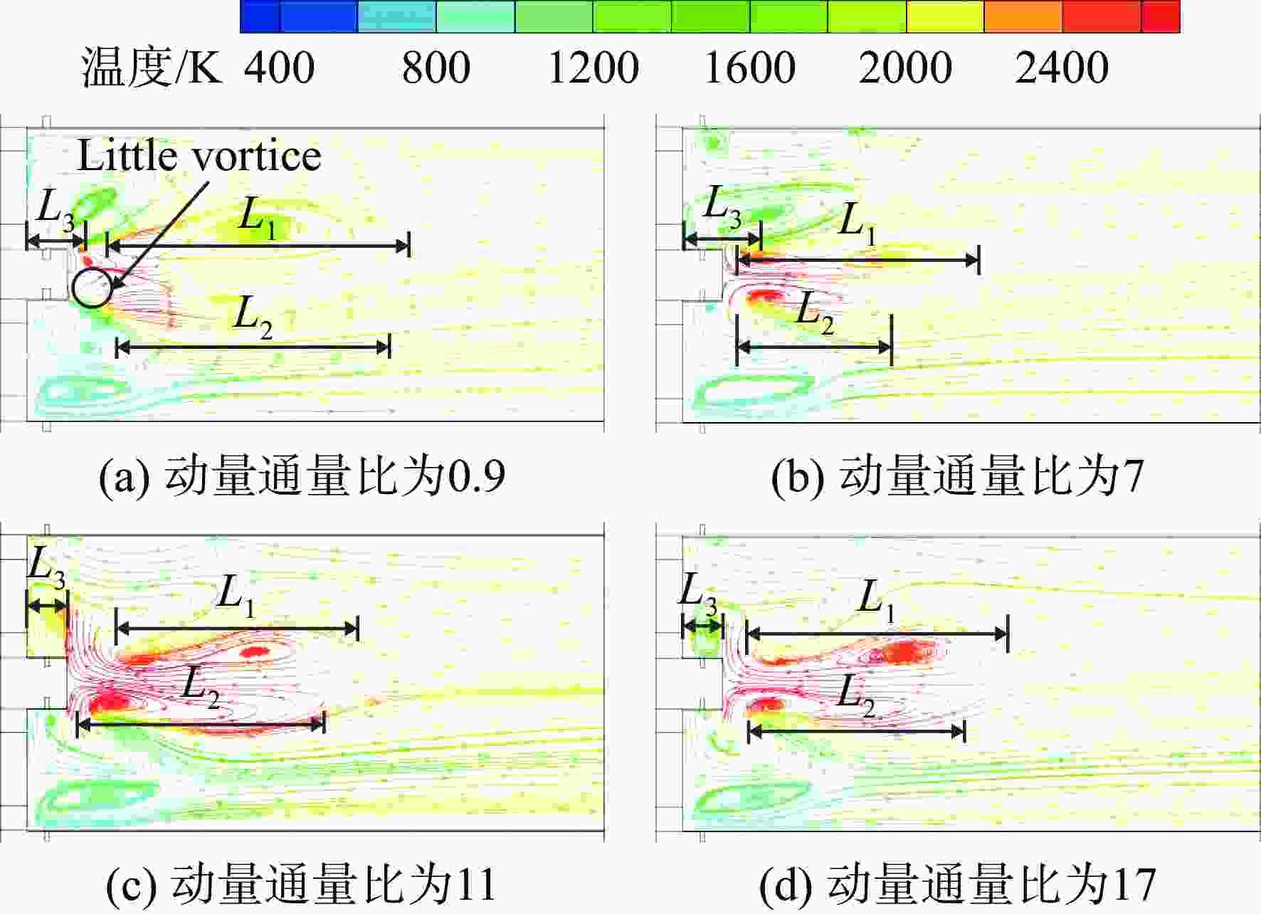
图 5 不同动量通量比下速度流线分布
Figure 5. Velocity streamline distribution for different momentum flux ratio
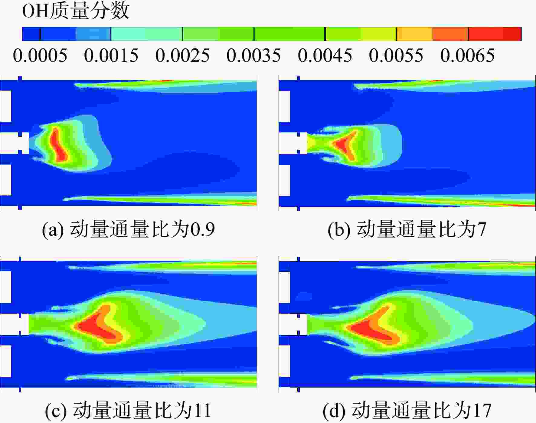
图 6 不同动量通量比下的OH质量分数分布
Figure 6. Mass fraction of OH distribution for different momentum flux ratio
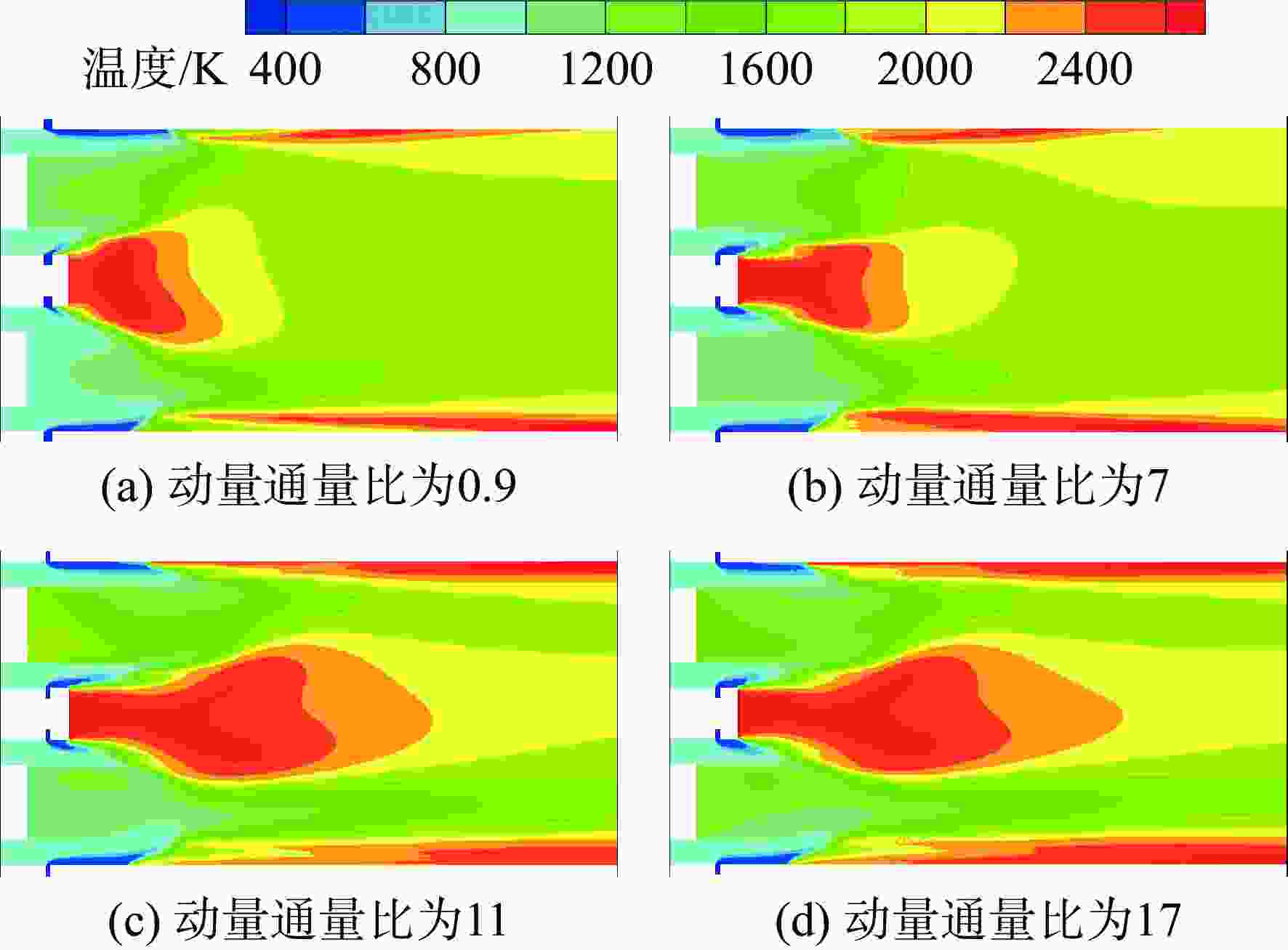
图 7 不同动量通量比下的温度分布
Figure 7. Total temperature distribution for different momentum flux ratio

图 8 不同动量通量比下的内外壁面平均温度
Figure 8. Average total temperature of wall surface for different momentum flux ratio
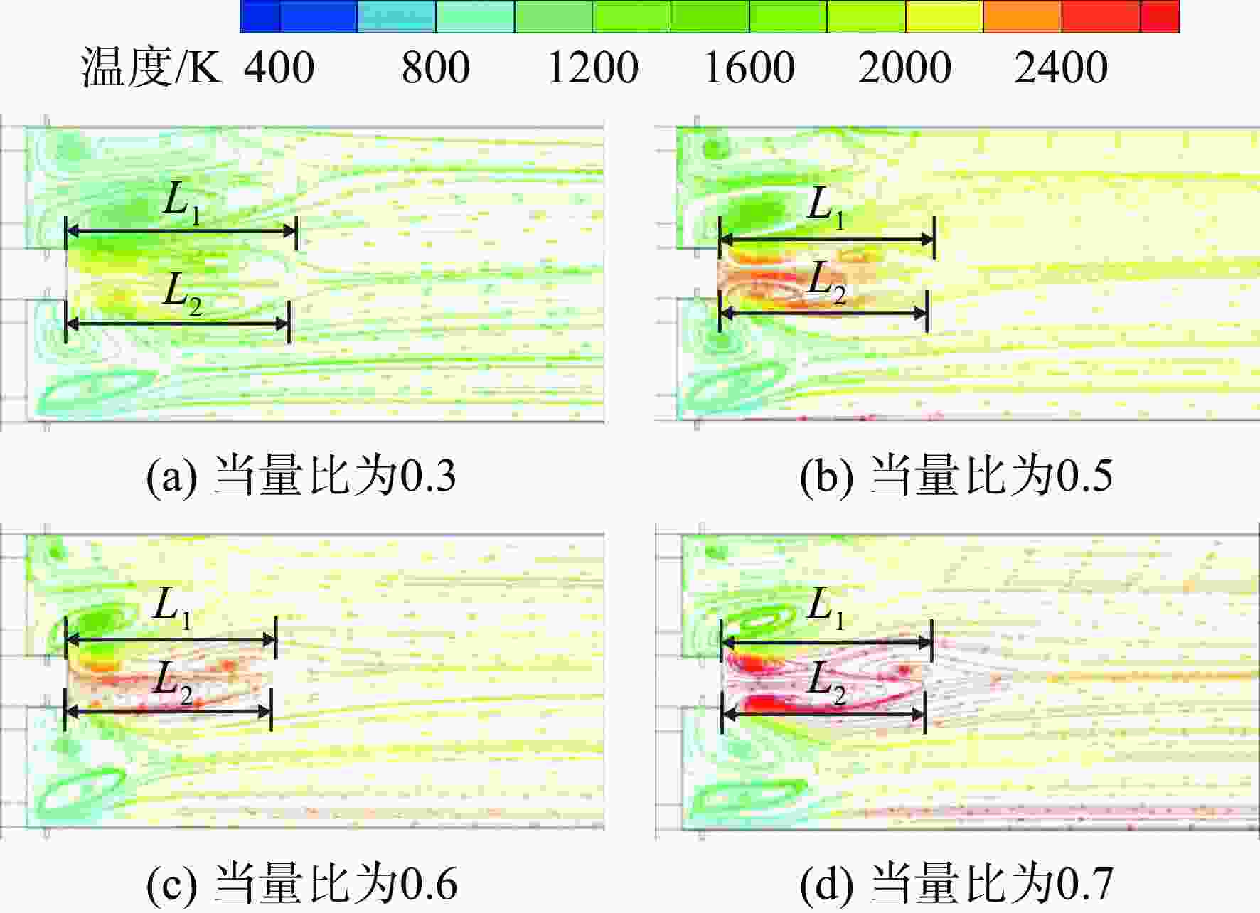
图 9 不同当量比下速度流线分布
Figure 9. Velocity streamline distribution for different equivalence ratio cases
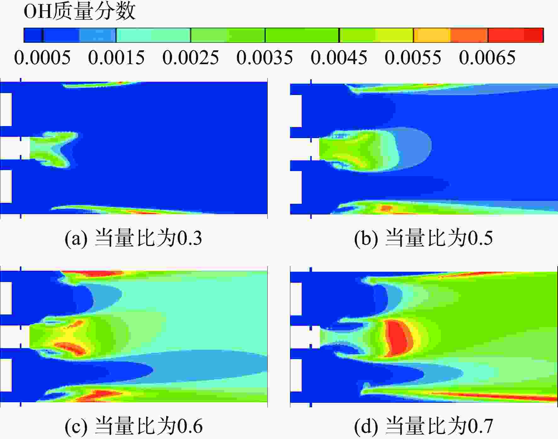
图 10 不同当量比下的OH质量分数分布
Figure 10. Mass fraction of OH distribution for different equivalence ratio cases
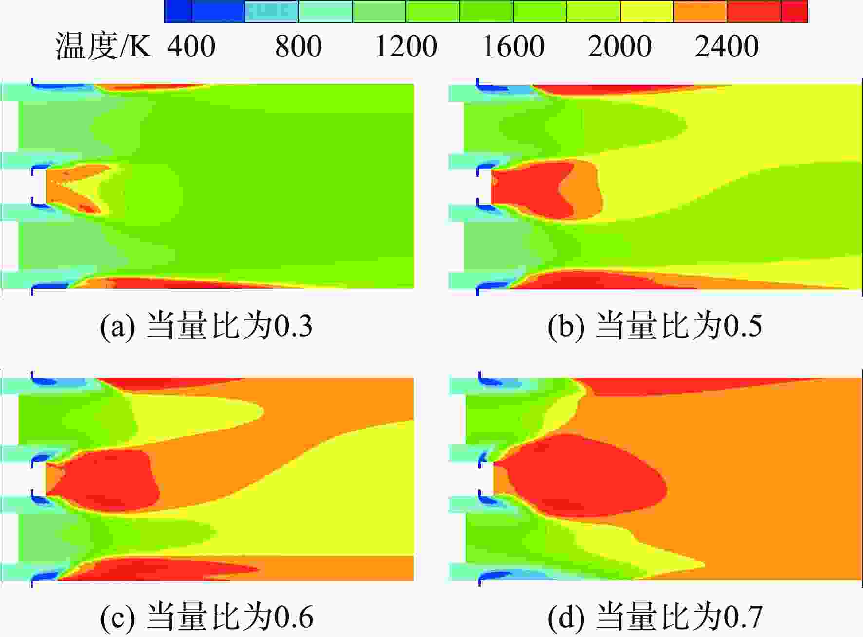
图 11 不同当量比下的温度分布
Figure 11. Total temperature distribution for different equivalence ratio cases
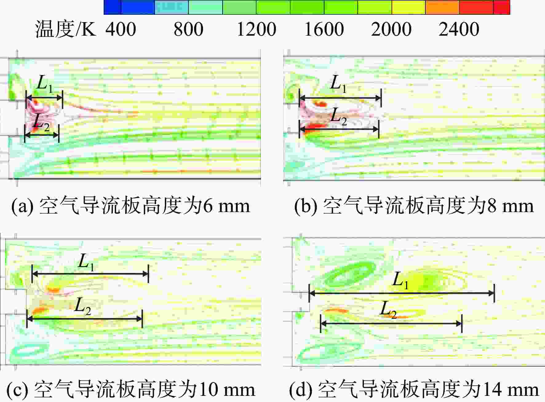
图 12 不同空气导流板高度下速度流线分布
Figure 12. Velocity streamline distribution for different air-gate cases
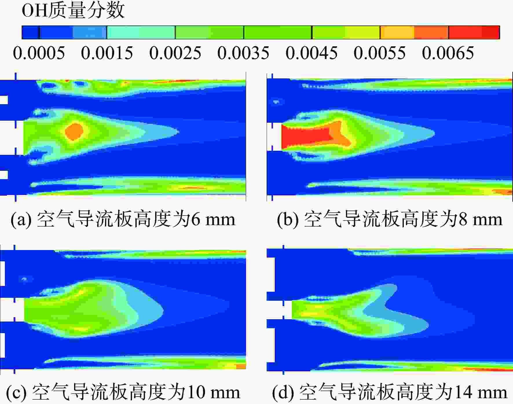
图 13 不同空气导流板高度下OH质量分数分布
Figure 13. Mass fraction of OH distribution for different hydrogen-gate cases
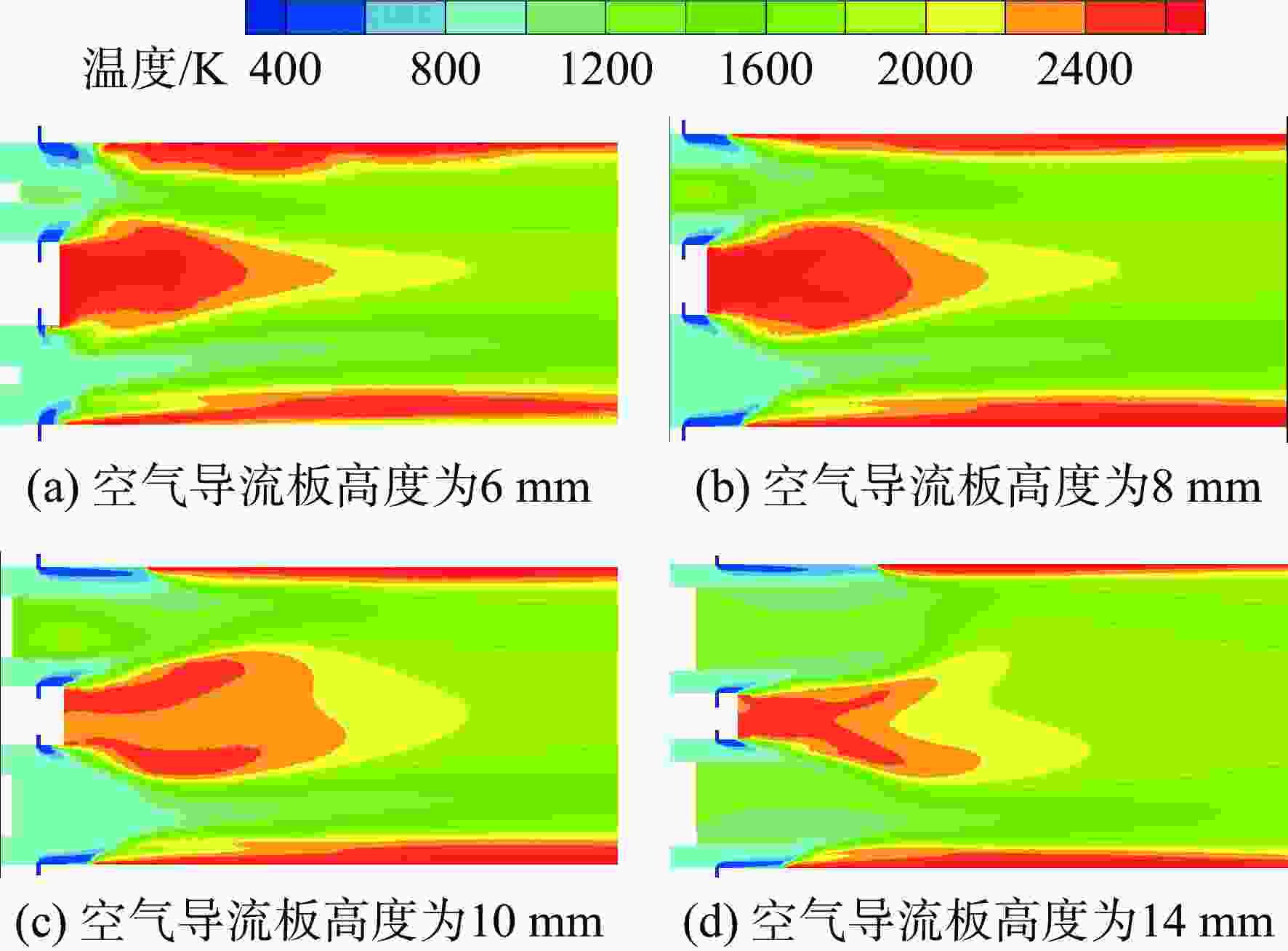
图 14 不同空气导流板高度下的温度分布
Figure 14. Total temperature distribution for different air-gate cases
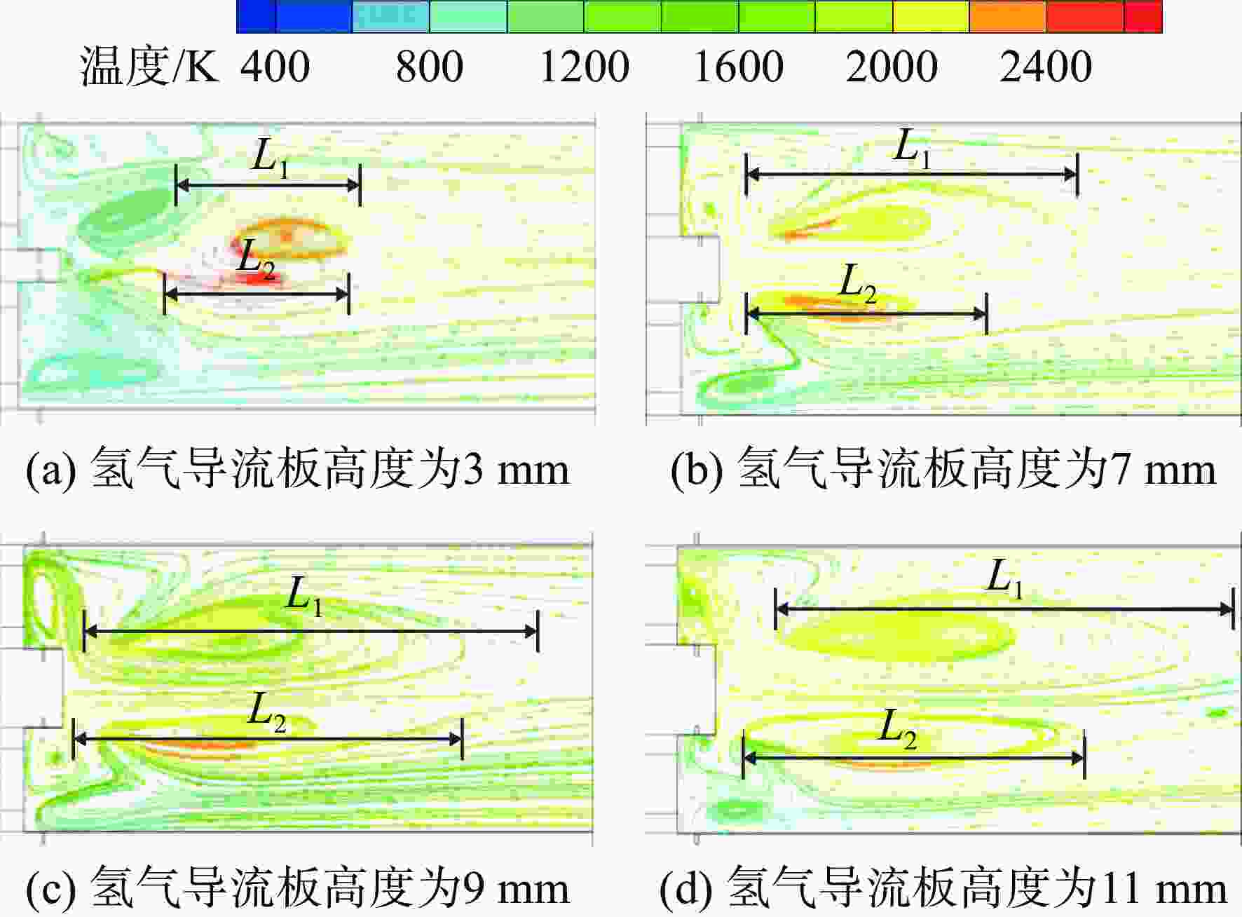
图 15 不同氢气导流板高度下速度流线分布
Figure 15. Velocity streamline distribution for different hydrogen-gate cases
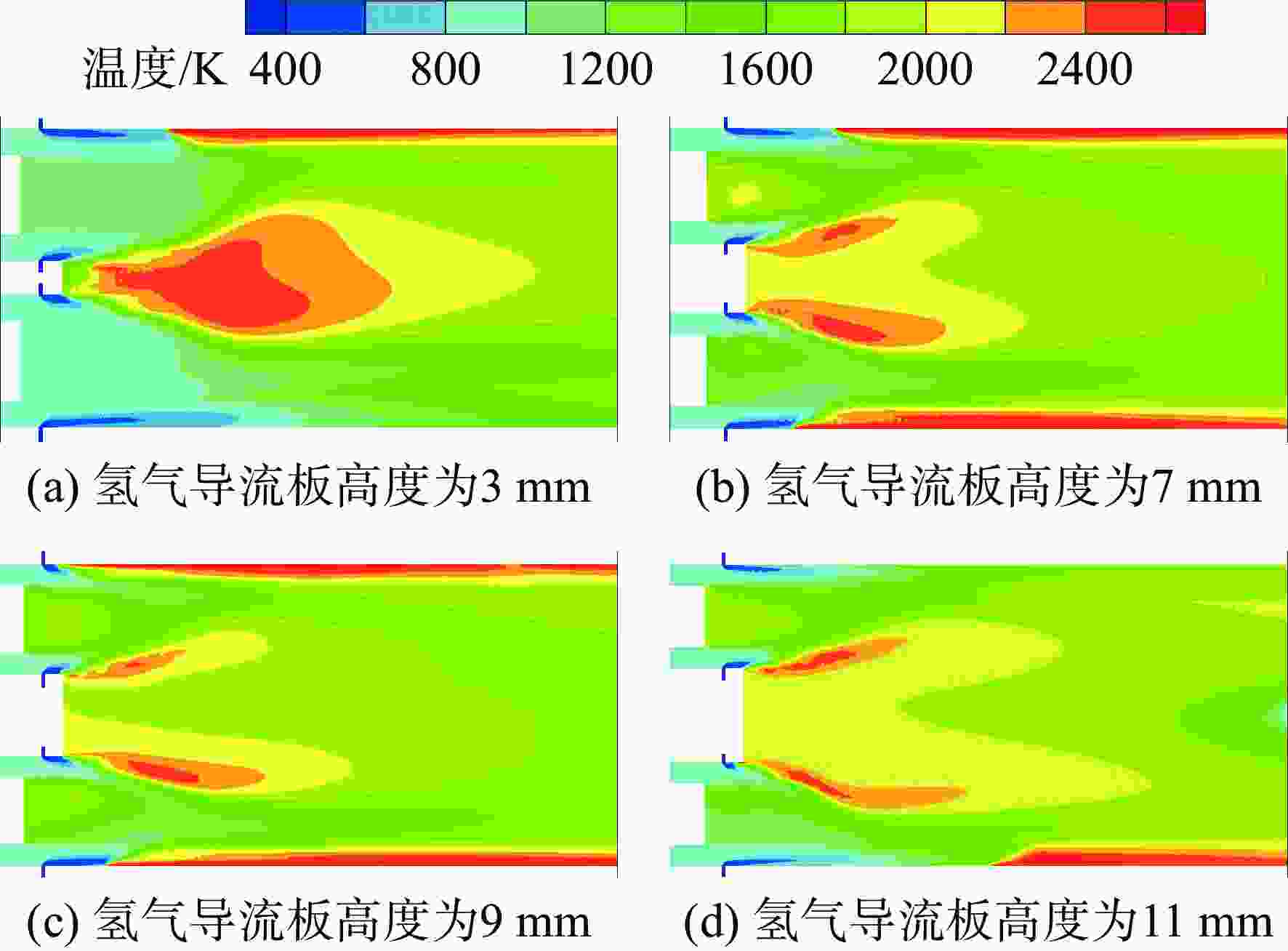
图 16 不同氢气导流板高度下的温度分布
Figure 16. Total temperature distribution for different hydrogen-gate cases
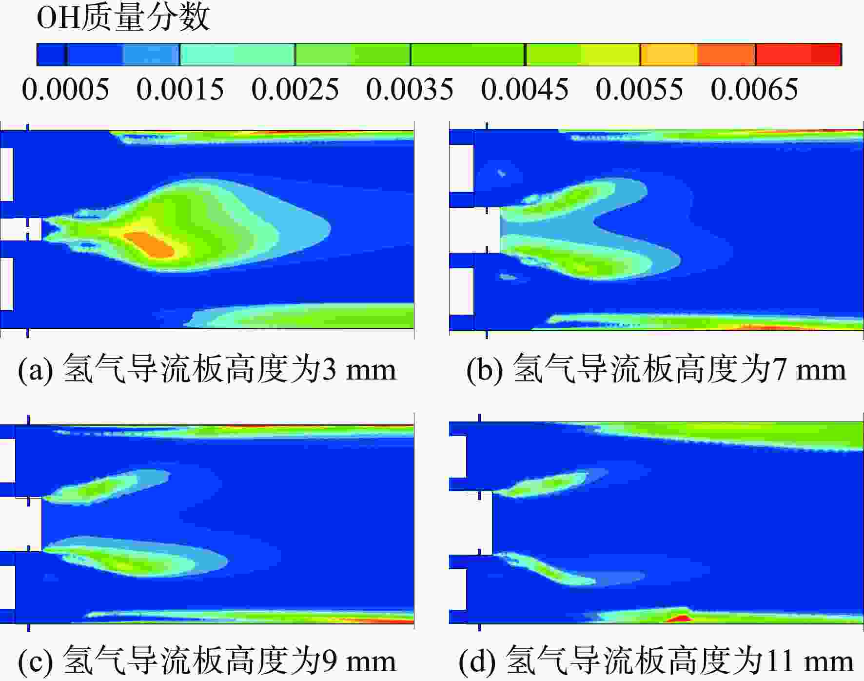
图 17 不同氢气导流板高度下OH质量分数分布
Figure 17. Mass fraction of OH distribution for different hydrogen-gate cases
序号 反应式 A/((cm3/mol)n−1/s) B E/(kJ/mol) 1 H+O2=O+OH 3.55×10¹⁵ −0.40 16.6 2 O+H2=H+OH 5.08×10⁴ 2.70 6.29 3 H2+OH=H2O+H 2.16×10⁸ 1.50 3.43 4 O+H2O=OH+OH 2.97×10⁶ 2.00 13.4 5 H2 +M=H+H+M 4.58×10¹⁹ −1.40 104 6 H2+Ar=H+H+Ar 5.84×10¹⁸ −1.10 104 7 H2+He=H+H+He 5.84×10¹⁸ −1.10 104 8 O+O+M=O2+M 6.16×10¹⁵ −0.50 0 9 O+O+Ar=O2+Ar 1.89×10¹³ 0 0 10 O+O+He=O2+He 1.89×10¹³ 0 0 11 O+H+M=OH+M 4.71×10¹⁸ −1.0 0 12 H+OH+M=H2O+M 3.80×10²² −2.0 0 13 H+O2(+M)=HO2(+M) 1.48×10¹² 0.6 0 14 H+O2(+M)=HO2(+M) 1.48×10¹² 0.6 0 15 HO2+H=H2+O2 1.66×10¹³ 0 0.823 16 HO2+H=OH+OH 7.08×10¹³ 0 0.295 17 HO2+O=O2+OH 3.25×10¹³ 0 0 18 HO2+OH=H2O+O2 2.89×10¹³ 0 0 19 HO2+HO2=H2O2+O2 4.20×10¹⁴ 0 12 20 HO2+HO2=H2O2+O2 1.30×10¹¹ 0 0 21 H2O2(+M)=OH+OH(+M) 2.95×10¹⁴ 0 48.4 22 H2O2+H=H2O+OH 2.41×10¹³ 0 3.97 23 H2O2+H=HO2+H2 4.82×10¹³ 0 7.95 24 H2O2+O=OH+HO2 9.55×10⁶ 2 3.97 25 H2O2+OH=HO2+H2O 1.00×10¹² 0 0 26 H2O2+OH=HO2+H2O 5.80×10¹⁴ 0 9.56  下载: 导出CSV
表 2 研究案例
Table 2. Investigation cases
工况编号 J Φ hair/mm h$_{{\rm{H}}_2}$/mm 1~4 0.9,7,11,17 0.4 12 5 5~8 17,46,67,91 0.3,0.5,0.6,0.7 12 5 9~12 30 0.4 6,8,10,14 5 13~16 30 0.4 12 3,7,9,11
下载: 导出CSV
-
[1] Advisory Council for Aeronautics Research in Europe. Flightpath 2050 Europe’s vision for aviation[M]. Luxembourg, the Grand Duchy of Luxembourg: Publications Office of the European Union, 2011. [2] 张弛,林宇震,徐华胜,等. 民用航空发动机低排放燃烧室技术发展现状及水平[J]. 航空学报,2014,35(2): 332-350.ZHANG Chi,LIN Yuzhen,XU Huasheng,et al. Development status and level of low emissions combustor technologies for civil aero-engine[J]. Acta Aeronautica et Astronautica Sinica,2014,35(2): 332-350. (in Chinese) [3] MAREK C, SMITH T, KUNDU K. Low emission hydrogen combustors for gas turbines using lean direct injection[R]. AIAA-2005-3776, 2005. [4] ZIEMANN J,SHUM F,MOORE M,et al. Low-NOx combustors for hydrogen fueled aero engine[J]. International Journal of Hydrogen Energy,1998,23(4): 281-288. doi: 10.1016/S0360-3199(97)00054-2 [5] 林宇震,李林,张弛,等. 液体射流喷入横向气流混合特性研究进展[J]. 航空学报,2014,35(1): 46-57.LIN Yuzhen,LI Lin,ZHANG Chi,et al. Progress on the mixing of liquid jet injected into a crossflow[J]. Acta Aeronautica et Astronautica Sinica,2014,35(1): 46-57. (in Chinese) [6] 张仪,王晓东,梁俊宇,等. 改进S-A湍流模型对横向射流的CFD模拟[J]. 航空动力学报,2017,32(11): 2761-2768.ZHANG Yi,WANG Xiaodong,LIANG Junyu,et al. CFD simulations of jet in cross-flow with modified S-a turbulence model[J]. Journal of Aerospace Power,2017,32(11): 2761-2768. (in Chinese) [7] 赵延辉,梁剑寒,闫田田. 涡流发生器控制下横向射流穿透特性及优化[J]. 航空动力学报,2016,31(4): 800-806.ZHAO Yanhui,LIANG Jianhan,YAN Tiantian. Penetration characteristics and optimization of transverse jet on condition of vortex generator[J]. Journal of Aerospace Power,2016,31(4): 800-806. (in Chinese) [8] FUNKE H, BOERNER S, KEINZ J, et al. Experimental and numerical characterization of the dry low NOx micro mix hydrogen combustion principle at increased energy density for industrial hydrogen gas turbine applications[R]. San Antonio, US: ASME Turbo Expo, 2013. [9] FUNKE H H W,KEINZ J,KUSTERER K,et al. Development and testing of a low NOx micromix combustion chamber for industrial gas turbines[J]. International Journal of Gas Turbine, Propulsion and Power Systems,2017,9(1): 27-36. doi: 10.38036/jgpp.9.1_27 [10] FUNKE H H W,BECKMANN N,KEINZ J,et al. Numerical and experimental evaluation of a dual-fuel dry-low-NOx micro mix combustor for industrial gas turbine applications[J]. Journal of Thermal Science and Engineering Applications,2019,11(1): 011015.1-011015.9. [11] MURTHY P. Numerical study of hydrogen micro-mix combustor for aero gas turbine engines[D]. Bedford, UK: Cranfield University, 2011. [12] KARAKURT A. Parametric investigation of combustion characteristics of a hydrogen micromix combustor concept[D]. Bedford, UK: Cranfield University, 2013. [13] ASANITTHONG S. Outlet temperature distribution control and heat transfer calculation for a hydrogen micro mix combustor[D]. Bedford, UK: Cranfield University, 2014. [14] SUN Xiaoxiao, AGARWAL P, CARBONARA F, et al. Numerical investigation into the impact of injector geometrical design parameters on hydrogen micromix combustion characteristics[R]. [S. l. ]: ASME Turbo Expo, 2020. [15] SUN Xiaoxiao, ABBOTT D, SINGH A V, et al. Numerical investigation of potential cause of instabilities in a hydrogen micromix injector array[R]. [S. l. ]: ASME Turbo Expo, 2021. [16] AGARWAL P, SUN Xiaoxiao, GAUTHIER P, et al. Injector design space exploration for an ultra-low NOx hydrogen micro mix combustion system[R]. Phoenix, US: ASME Turbo Expo, 2019. [17] 王阳墚旭,陈洁,马榕谷,等. 燃氢燃气轮机燃烧室结构改进[J]. 热力发电,2016,45(8): 53-57. doi: 10.3969/j.issn.1002-3364.2016.08.053WANG Yangliangxu,CHEN Jie,MA Ronggu,et al. Structure modification for combustor in gas turbine turning to burn hydrogen gas[J]. Thermal Power Generation,2016,45(8): 53-57. (in Chinese) doi: 10.3969/j.issn.1002-3364.2016.08.053 [18] 田晓晶,崔玉峰,房爱兵,等. 预混段结构对氢燃料旋流预混燃烧诱导涡破碎回火极限影响的数值研究[J]. 中国电机工程学报,2014,34(8): 1276-1284.TIAN Xiaojing,CUI Yufeng,FANG Aibing,et al. Numerical investigation on the effects of mixing zone structure on combustion induced vortex breakdown flashback limits of a swirl-premixed hydrogen flame[J]. Proceedings of the CSEE,2014,34(8): 1276-1284. (in Chinese) [19] 于宗明,吴鑫楠,邱朋华,等. 燃气轮机富氢燃料预混燃烧实验研究[J]. 中国电机工程学报,2017,37(5): 1426-1434.YU Zongming,WU Xinnan,QIU Penghua,et al. Experimental study on premixed combustion for gas turbines burning high hydrogen fuels[J]. Proceedings of the CSEE,2017,37(5): 1426-1434. (in Chinese) [20] MO Da. Conceptual design of a two-shaft high bypass turbofan engine for entry-into-service 2025[D]. Bedford, UK: Cranfield University, 2021. [21] FLUENT Incorporation. FLUENT 6.3 user’s guide[R]. New Hampshire, US: FLUENT Incorporation, 2006. [22] ANASYS Incorporation. ANSYS Chemkin tutorials manual[R]. San Diego, US: ANASYS Incorporation, 2016. [23] GAUTHIER P Q. Comparison of temperature fields and emissions predictions using both an FGM combustion model, with detailed chemistry, and a simple eddy dissipation combustion model with simple global chemistry[C]//Proceedings of ASME Turbo Expo: Turbomachinery Technical Conference and Exposition. Charlotte, US: ASME, 2017: 1-14. [24] BRAND J, SAMPATH S, SHUM F, et al. Potential use of hydrogen in air propulsion[R]. AIAA-2003-2879, 2003. -


 点击查看大图

计量
- 文章访问数: 942
- HTML浏览量: 612
- PDF量: 195
- 被引次数: 0