Shock-wave/boundary-layer interactions on wedge with sawtooth leading edge
-
摘要:
为探究三维锯齿构型对入射激波/边界层干扰流场结构的影响,对一种前缘带锯齿的斜楔/底板流场进行数值仿真分析,并总结了不同锯齿深度对流场的影响规律。结果表明:与前缘平直斜楔相比,锯齿斜楔受溢流的影响。入射激波呈现为三波系曲面结构,激波强度减弱,波角减小,流场结构后移;底板上分离区呈现出“凹”型的空间结构,分离区展向表现为中间低、两边高,流向表现为中间短,两边长。随着锯齿深度增大,流场结构更加后移,分离区的三维特性更加明显。在溢流模型中,受侧面溢流影响,对称面处的分离最大,分离区呈现出三维的“半凹”结构;对比基准溢流模型,锯齿溢流降低了入射波系强度,使侧面溢流减少。
Abstract:In order to investigate the influence of three-dimensional sawtooth configuration on the flow field structure of incident shock-wave/boundary-layer interaction, the flow field of wedge with sawtooth leading edge/plate was numerically simulated and analyzed, and the influence laws of different sawtooth depths on the flow field were summarized. The results showed that, compared with the wedge with straight leading edge, the sawtooth wedge was affected by overflow. Meanwhile, the incident shock wave presented a curved three-wave structure, the shock wave intensity was weakened, the wave angle was reduced, and the flow field structure moved backward; the separation zone on plate presented a “concave” spatial structure. The spreading direction of the separation zone was low in the middle but high on both sides, and the flow direction was short in the middle but long on both sides. With the increase of sawtooth depth, the flow field structure moved backward, and the three-dimensional characteristics of the separation zone became more obvious. In the overflow model, due to the side overflow, the separation at the symmetrical plane was the largest, and the separation zone presented a three-dimensional “semi concave” spatial structure. Compared with the original overflow model, the sawtooth overflow reduced the intensity of the incident wave system and the side overflow.
-
激波/边界层干扰现象普遍存在于超声速和高超声速飞行器飞行过程的内外流场中[1]。由于超/高超声速进气道的减速增压工作特点,进气道内会存在激波系,而气体的黏性会使其在固体壁表面发展出边界层,两者发生干扰可能引起流动分离,从而导致进气道流通截面减小、总压恢复下降,甚至不起动等问题[2-4]。因此激波/边界层干扰是研究超声速和高超声速飞行中的基础问题之一。
为了分析实际流动过程中的激波/边界层干扰现象,学者们提炼出了一系列经典的激波/边界层干扰构型。其中,斜楔/平板构型是一种最常见的入射斜激波/边界层干扰构型[5-6]。前人对该构型开展了丰富的理论、数值以及实验研究,包括流场的流动分离准则[7],分离区内流动特征、压升/热流规律[8],分离区非定常特性[9]等。这些成果促进了人们对激波/边界干扰流动机理的认知,并广泛应用在了实际飞行器的工程设计与优化中。
超/高超声速进气道唇口入射激波与肩部边界层的干扰是超/高超声速进气道的设计关键技术之一,该干扰容易引起分离,从而影响进气道的气动性能[10]。为了提高进气道的性能,学者们在控制进气道内部激波/边界层干扰方面做了许多研究。例如,在对定几何进气道唇口结构研究中,内转式进气道构型的V形溢流唇口[11-12]可改善进气道内的流动结构。国防科学技术大学的王翼[13]通过实验研究了不同唇口角情况下二元进气道的起动性能,发现在内收缩比不变的情况下,唇口内角度对进气道起动的影响不大。西北工业大学的石磊等[14]通过剪切二元进气道唇口牺牲一部分流量的情况下降低了进气道的自起动马赫数,拓宽了进气道的工作范围。南京航空航天大学的郭金默等[15]通过数值仿真研究了锯齿状唇口对轴对称进气道的性能影响,研究发现锯齿状唇口是一种有效降低进气道自起动马赫数、提高总压恢复的方案。综上可知,随着设计水平的提高,进气道唇口由平直二维结构向三维结构发展,其所带来的入射激波/边界层干扰流动与前期研究存在差异[16-18],带来了新的激波/边界层干扰问题[19-20],有必要对其开展深入研究。
为了探究三维锯齿构型对入射激波/边界层干扰的影响,本文设计了一种前缘带锯齿的斜楔/底板构型,采用数值仿真的方法研究其激波/边界层干扰产生的流场结构,并开展锯齿构型的几何参数变化对流场影响规律的研究。
1. 物理模型与计算方法
1.1 物理模型
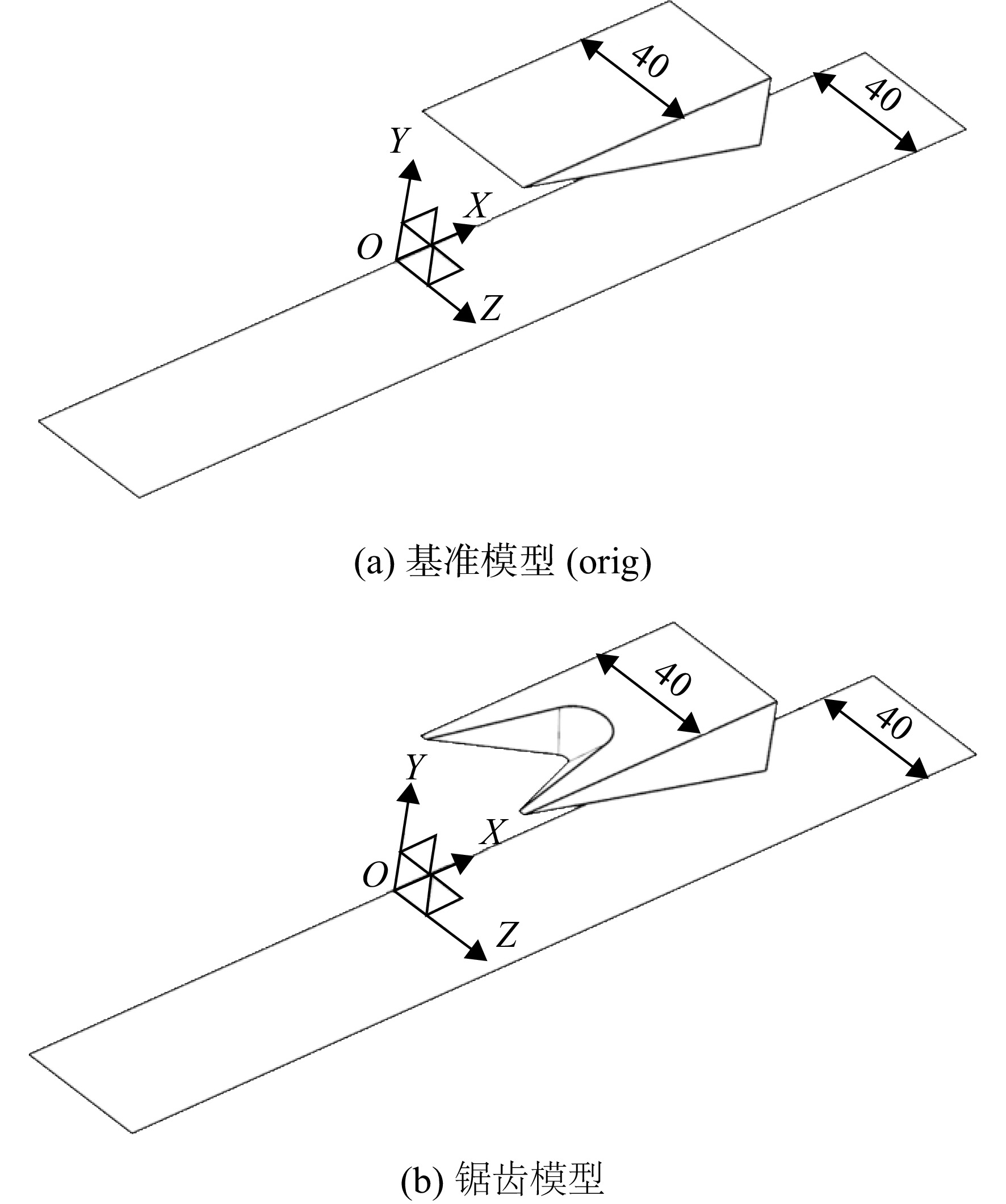
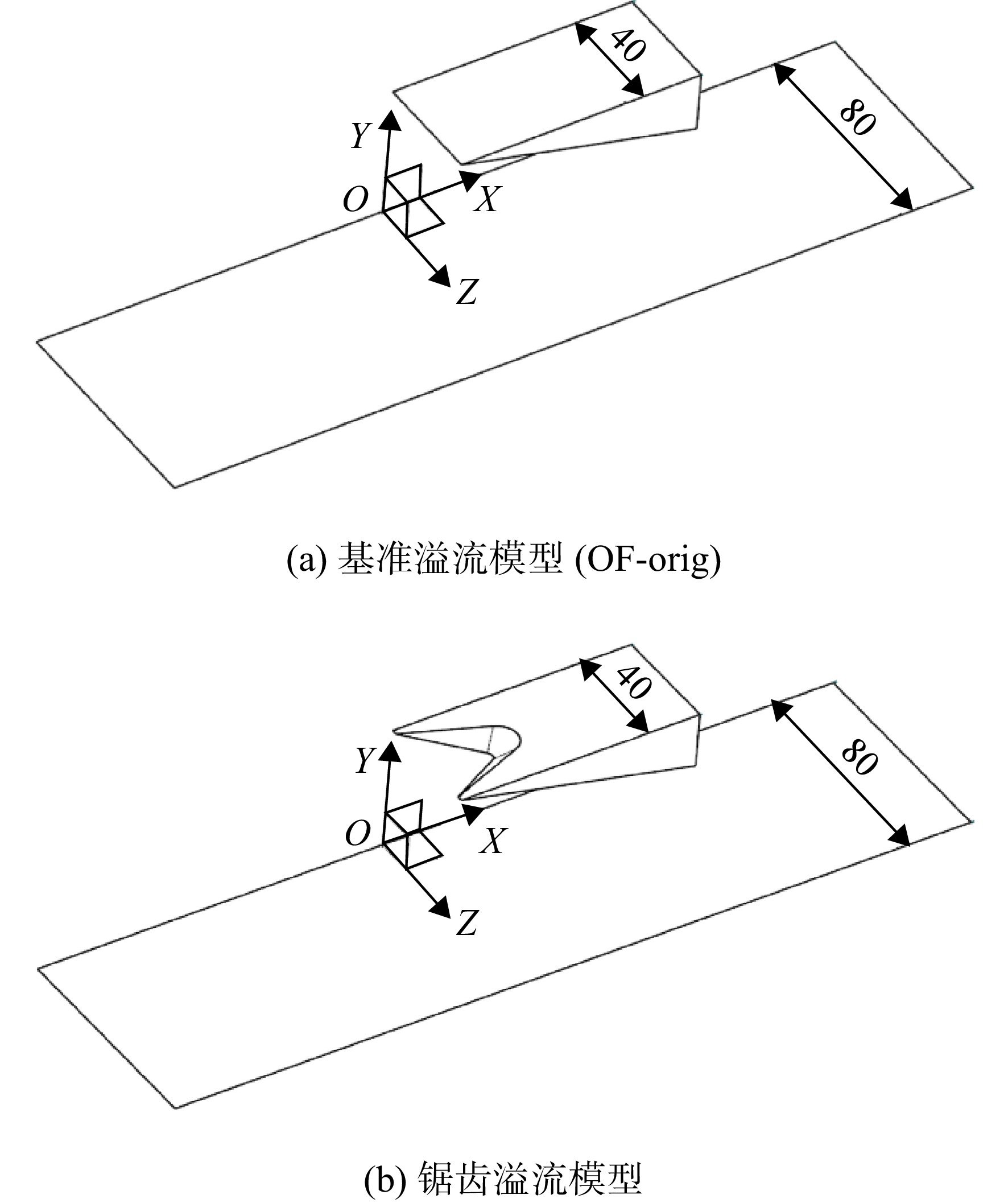
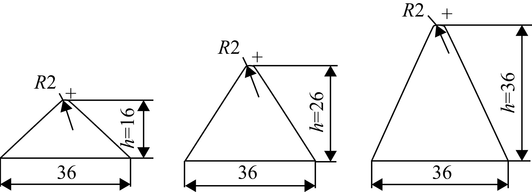
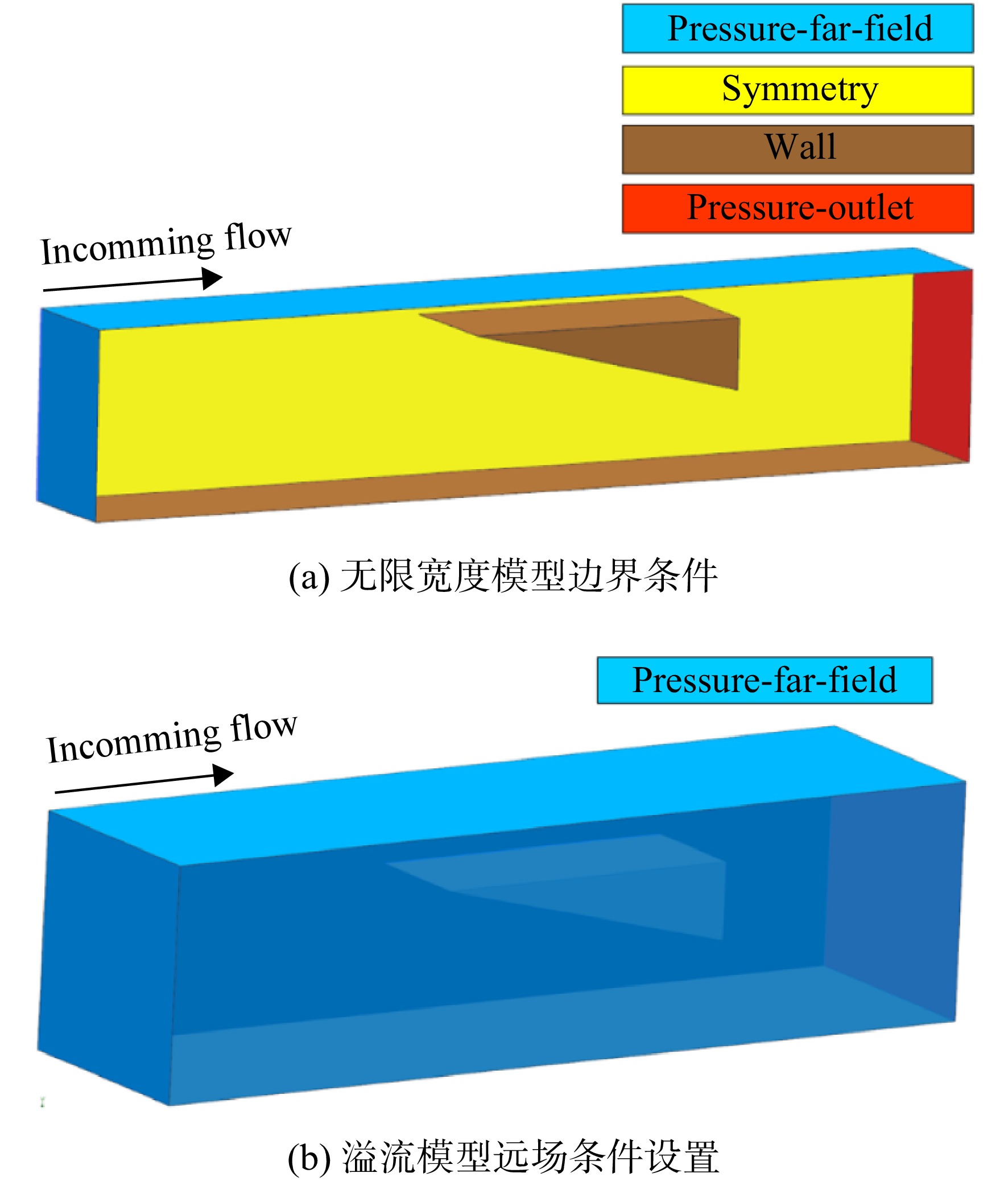
为了对比分析锯齿构型几何参数变化对流场结构的影响,本文基于斜楔/底板模型开展了研究。图1是所采用斜楔/底板的侧面尺寸,各模型相同,图中α为各模型中斜楔的前缘压缩角,斜楔前缘距底板的高度为50 mm。图2为无限宽度的斜楔/底板模型,图2(a)为斜楔前缘平直的基准模型(orig),图2(b)为斜楔前缘带锯齿的锯齿模型,后文中用锯齿深度缩略表示。图3为有限宽度的溢流模型,图3(a)为平直前缘的基准溢流模型(OF-orig),图3(b)为锯齿前缘溢流模型,溢流模型的底板宽度为两倍的斜楔宽度。图4为锯齿深度h=16,26,36 mm的锯齿剪切平面草图。前缘的锯齿是由斜楔下表面的锯齿草图进行偏置拉伸并与斜楔体求差获得,拔模从起始限制,角度为−40°。锯齿齿宽均为36 mm,单个斜楔宽度为40 mm,楔前缘两侧未剪切部分宽度为2 mm。X轴正向为来流方向,Y轴为纵向,Z轴为来流的展向。
1.2 计算方法与验证
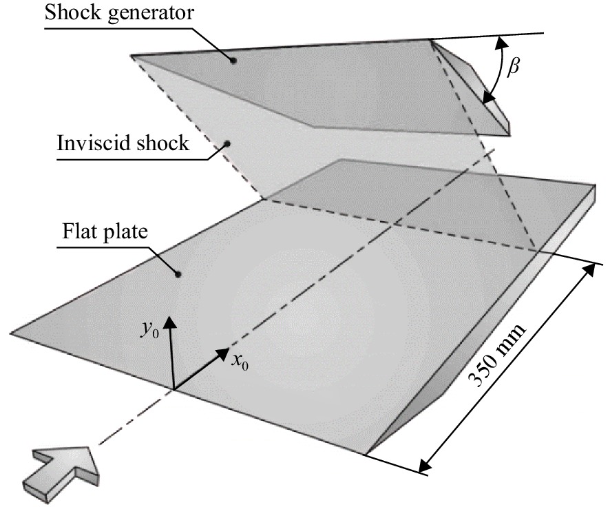
本文求解三维定常雷诺平均Navier-Stokes 方程来模拟真实流场,空间离散选择二阶迎风格式,湍流模型为标准κ-ε模型,壁面选择无滑移绝热壁面,流体条件为定比热比理想气体,其分子黏性遵照Sutherland三阶公式计算。为了验证本文所采用数值仿真方法的可靠性,选取文献[6]中的几何构型进行数值仿真方法校验。图5为文献[6]中实验所用的斜楔/底板模型,位于平板上方的压缩面角度可调,文献中分别开展了6°、10°和14°这3种压缩角方案研究。本文选取14°压缩角对数值仿真方法进行验证,仿真计算参数设置与实验完全相同:来流马赫数为5,来流总压
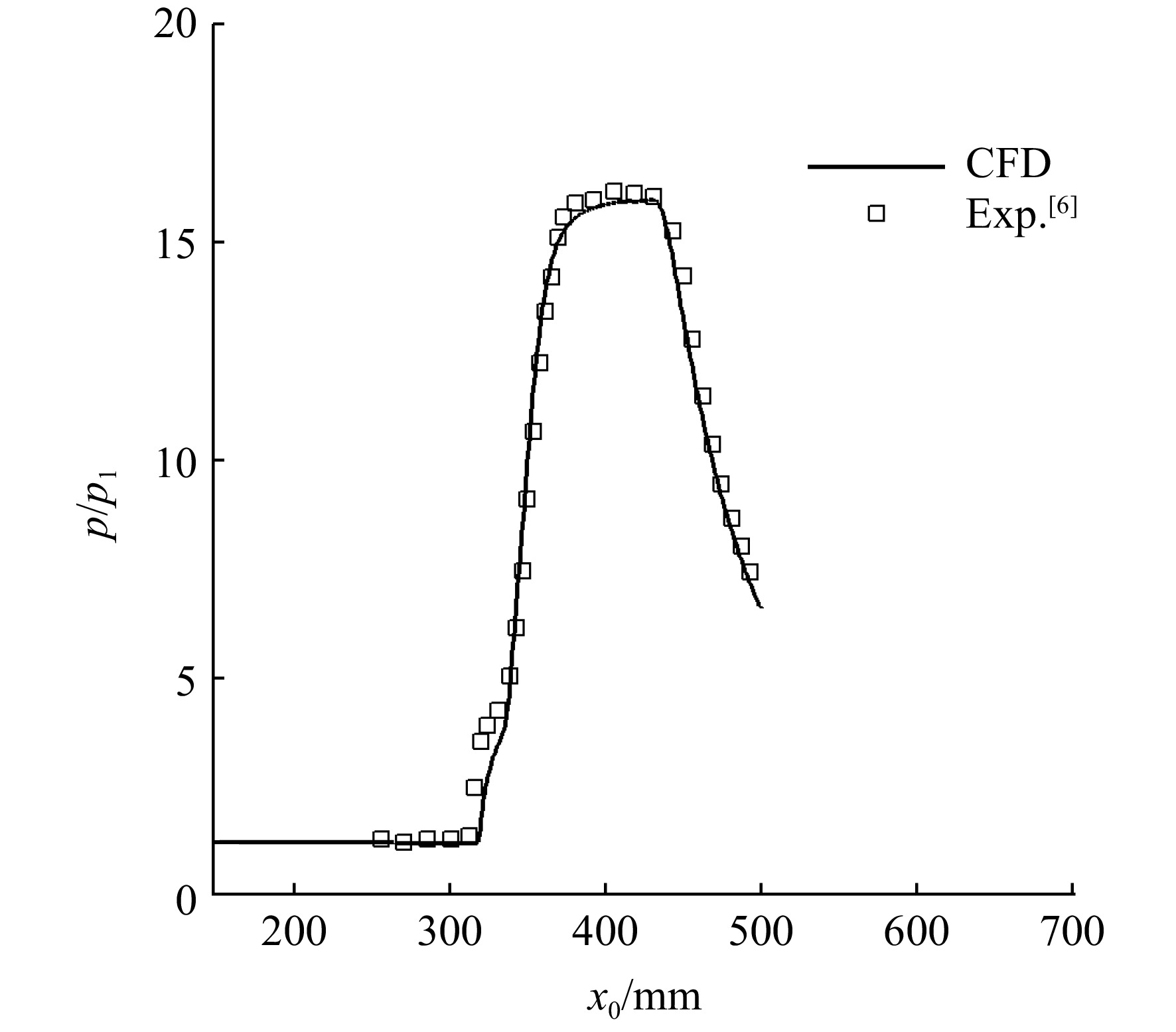
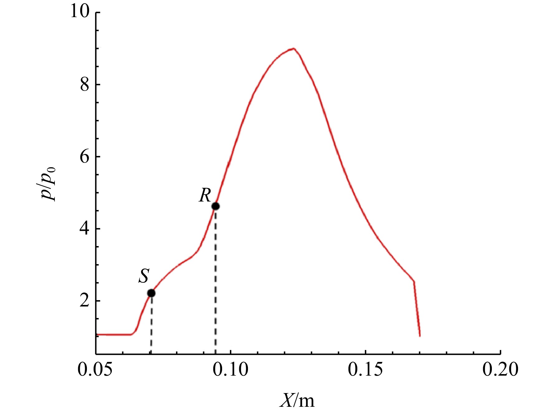
p∗1 =2120 kPa,来流静压p1 =4006.9 Pa,总温T∗1 =410 K。图6为仿真结果与实验的流场结构对比,可以看出仿真与实验的波系结构一致,从图6(b)中可以看出,数值仿真计算得到的分离区起始点S、再附点R位置与实验基本吻合。图7为数值仿真(CFD)与实验(Exp.)的壁面压力变化趋势,纵坐标展示了静压(p)与实验中来流静压(
p1 )的比值,横坐标x0 为实验模型底板上的流向长度,可以观察到两者变化趋势和压比值吻合较好,由此说明本文所采用的标准κ-ε湍流模型具有较高的可信度。对于计算网格的合理性,选择基准模型的网格进行无关性验证。近壁面网格采用加密处理,第1层网格法向高度取0.1 mm,壁面
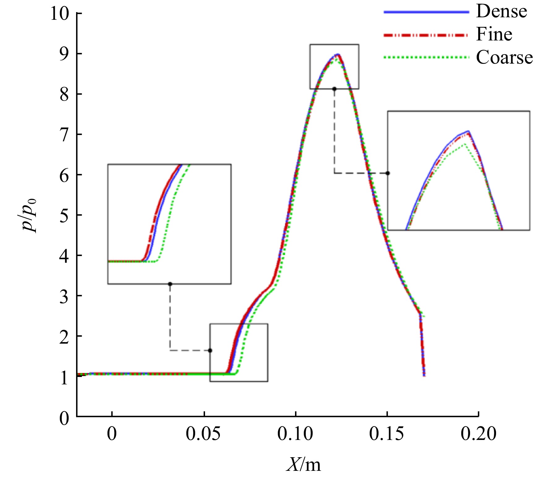
y+ 值满足湍流模型。表1给出了粗网格(coarse)、中等网格(fine)和密网格(dense)这3种网格的网格量设计。本文各模型仿真计算所用的流场参数见表2,其中Ma∞ 为来流马赫数,p0 为来流静压,T∞ 为来流静温,p∗ 为来流总压。图8为不同密度网格原始模型底板静压比分布曲线,纵坐标展示了静压(p)与来流静压(p0 )的比值,横坐标X为原始模型底板上的流向长度。可以观察到中等网格与密网格压比分布基本重合,而粗网格的计算结果偏差较大。综合考虑计算精度与效率,选择380万网格量的中等网格为基础来设置其他算例网格是合适的。表 1 网格量设计Table 1. Mesh quantity design网格密度 网格量/104 粗网格 180 中等网格 380 密网格 500 表 2 流场参数Table 2. Flow field parametersMa∞ p0/Pa T∞/K p*/Pa 3.8 3645 122.05 422415.1 1.3 边界条件设置
为减少其他因素对入射激波与边界层的影响,仿真计算中各模型的侧滑角与攻角均为0°。图9给出了计算域及边界条件设置,前方设置压力远场(pressure-far-field)以提供超声速来流,出口为压力出口(pressure-outlet)边界,压力值设置与外界环境压力相同,以形成通流流场。图9(a)中无限宽度模型的两侧均为对称面Symmetry,而在溢流模型中,贴近斜楔一侧为对称面,另一侧为压力远场边界,其分布如图9(b)所示,其他边界条件分布与无限宽度模型一致。计算收敛准则是监测残差下降四个数量级,出口质量流量稳定。
2. 计算结果及分析
2.1 无限宽度的基准模型与锯齿模型流场结构
本文仿真计算所得的流场结果均为来流马赫数
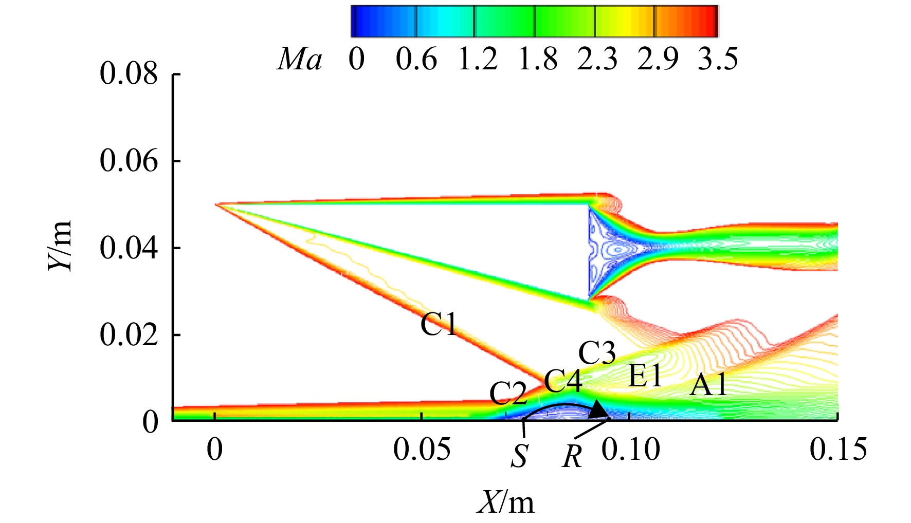
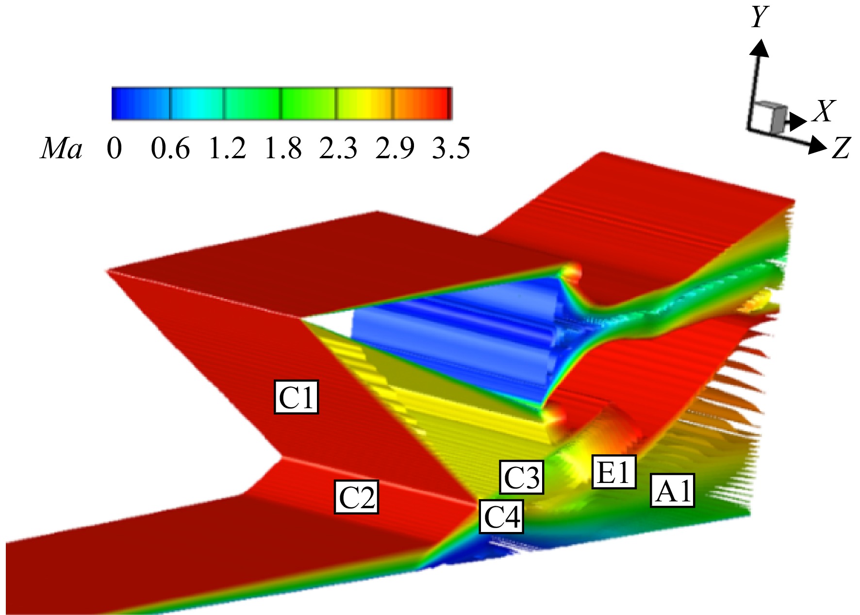
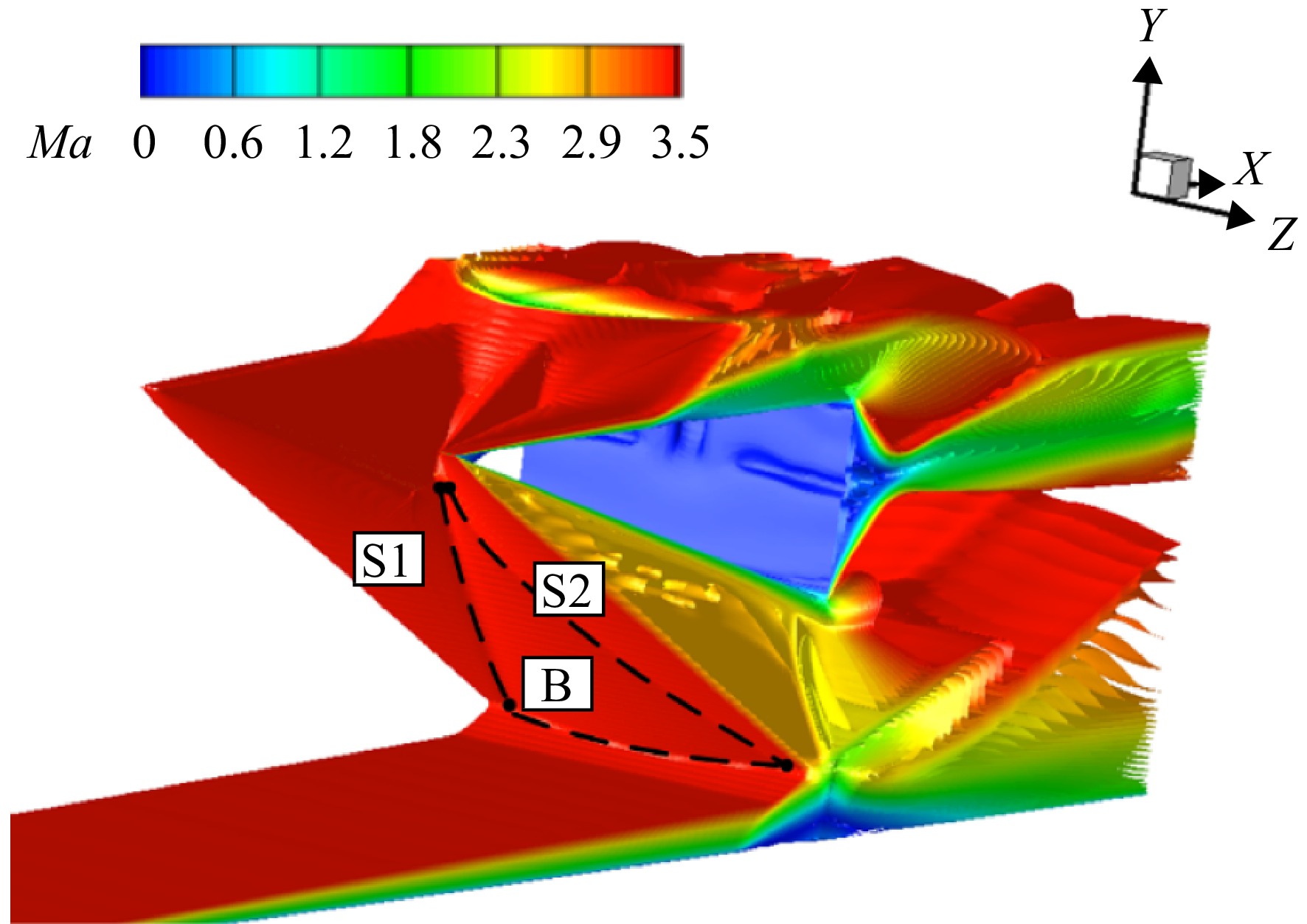
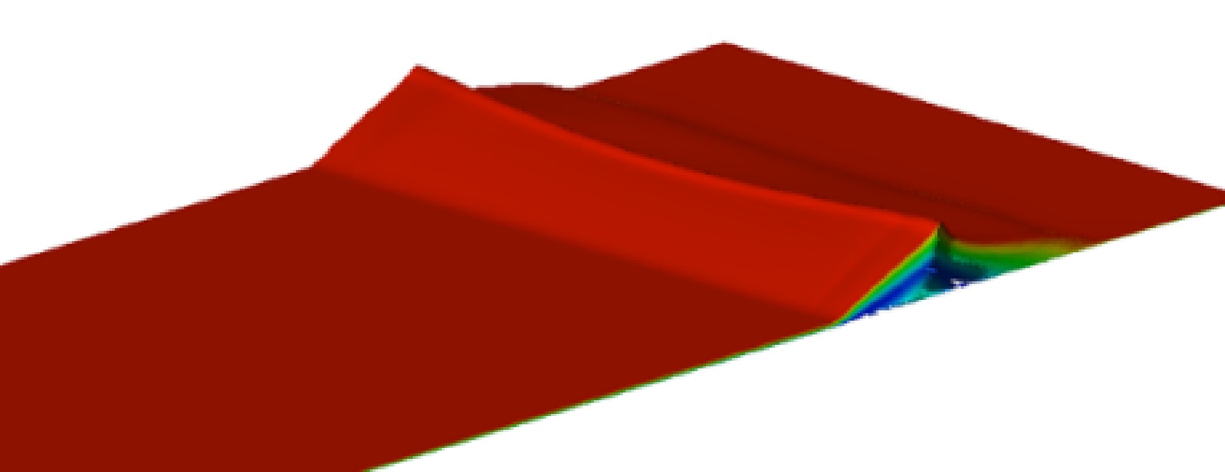
Ma∞ =3.8下模型所产生的流场。图10为基准模型在来流下的马赫数等值线分布,从图中可以看出,来流在斜楔前缘处产生一道入射激波C1,该激波入射到底板上,与底板边界层发生干扰。在入射激波强逆压力梯度影响下,边界层内部的亚声速流出现逆流,产生回流区。分离起始点S到再附点R之间为回流区,回流区内部存在低能流旋涡,在旋涡顶部与主流相互剪切的流线为分离流线,该流线可以反映分离区的分布范围。由于回流区的凸起结构形成了气动型面,气流经过其上方产生诱导激波C2,并与入射激波C1相交透射出斜激波C3、C4,射向分离区的斜激波C4经过气动表面后反射为膨胀扇E1,气流经过该膨胀扇加速方向发生改变,使分离区再附于壁面,再附点R位于旋涡的末端,再附后分离区域减小,使得气动流道拓宽,高速气流朝壁面处偏转在回流区下游形成再附激波A1,波后的高压区域为再附区。图11为基准模型底板静压比沿程分布曲线,图中p/p0 为静压与来流静压比,从曲线图中可以观察到静压比在分离起始位置S点前发生阶跃,而后在分离区内增长逐渐变缓,这是因为膨胀波的减压作用使激波的增压速率减缓;再附点R前曲线斜率又增大是受到了再附激波的影响;在压比曲线最高点后出现压降是由于楔尾膨胀波对底板边界层的干扰,使静压比快速下降。图12为基准模型在来流下产生流场的马赫数等值面的空间分布,观察到入射激波C1为平面状态,波系结构具有二维性。图13为锯齿模型马赫数等值面分布,锯齿模型入射激波由基准模型的平直波面变为三维曲面激波,其组成为锯齿两侧后掠前缘产生的两道曲面激波S1、S2,S1与S2激波间发生强干扰产生类于“桥激波”的B激波(三角虚线区域)。图14为底板分离区的空间分布,分离区沿展向呈中部低、两侧高的“凹”型。
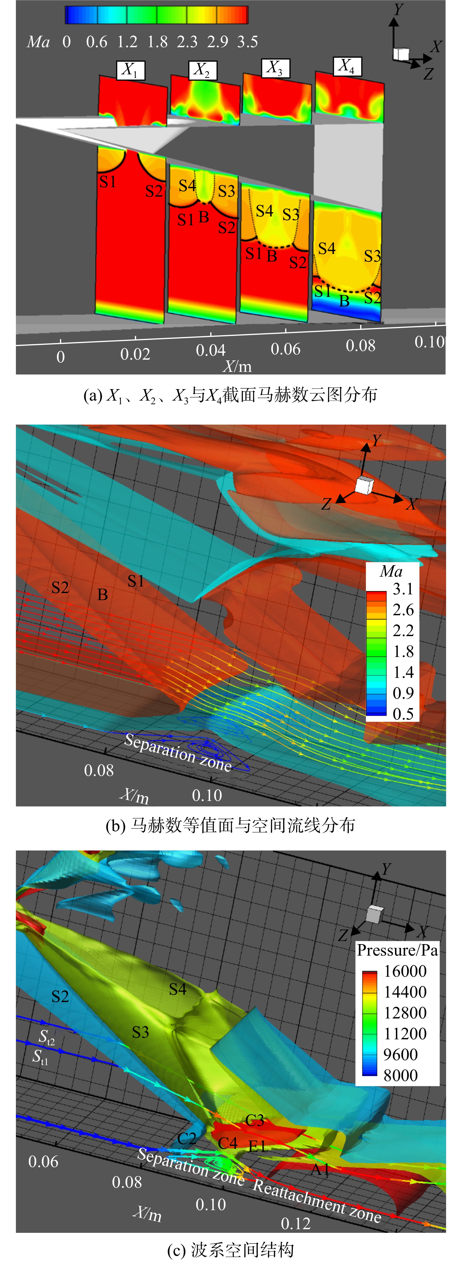
由于锯齿模型流场结构具有三维性,为进一步分析,在图15(a)中,以斜楔前缘为起始截取X为法向的参考平面X1(X=30 mm)、X2(X=50 mm)、X3(X=70 mm)与X4(X=90 mm),图中入射波面分为粗虚线的“桥激波”B,粗实线的曲面激波S1、S2。在X1处,远处来流先与两侧未被剪切斜楔壁面发生碰撞产生斜激波,但此时斜楔中间被剪切的部分仍为未压缩自由来流,静压较低,所以两侧波后高压气流往中间流动,形成曲面激波S1、S2,X1截面两道曲面激波相隔较远未相互干扰;随着两侧激波S1、S2、不断向下游发展,两者距离缩小直至交汇并在中间位置处产生干扰“桥激波”B,在X2参考面上其范围要小于两侧S1、S2激波,图15(a)云图与图15(b)空间流线上马赫数分布均反映激波B后马赫数要低于S1、S2,而来流条件相同,故激波B强度要高于两侧S1、S2;在X3平面上,激波B影响范围增大并挤占两侧曲面激波S1、S2,三道波面分布范围相近;到下游X4处, 激波B后高压区域进一步扩大,占据绝大部分流场,强度有所减弱。图15(b)中底板附近的干扰处,分离区域后段与入射波面相适配,分离后段也具有 “凹”型分布规律。
图15(c)为锯齿模型波系的空间结构。由于 “桥激波”B强度大于两侧的曲面激波S1、S2,导致入射激波后压力不连续,为了平衡区间差异,三道波面后不同区间边界上有两道类锥形的曲面压缩波S3、S4(图15(a)中细虚线位置),随着入射激波向下游延伸,该压缩波影响区域随B激波不断向下游发展,从空间角度来看,该压缩波在靠近底板处对模型两侧波系影响最大。靠近对称面处的空间流线St1上静压分布显示了气流经过入射波面S2后又被S3再次压缩,其次再经过C3;而位于流场中部的St2流线经入射波面B压缩后受到该压缩波的影响较少,表现为B激波后气流在向下膨胀过程中静压明显降低,曲面激波S1、S2后气流流经压缩波S3、S4后静压继续升高。该发展变化导致了透射激波C3波前气流参数分布得不均匀,即两侧气流静压较高,中部静压低,该影响又经过下游的膨胀扇E1与再附激波A1传递到底板上的再附区域,经由底板边界层内的亚声流动前传到上游的分离区域。
图16(a)为锯齿模型底板表面的极限流线与线上压比分布,其中参考线Z1(Z=20 mm)、Z2 (Z=30 mm)、Z3(Z=40 mm)。图中分离区的分离线位于上游且为平直状态,再附线弯曲,再附线上存在压力梯度,即两侧压比较高,中部低,高压比处有较大的回流跨度。图16(b)为锯齿模型分离区内流线分布,旋涡展向高度分布变化,两侧高中间低,流动具有三维性。
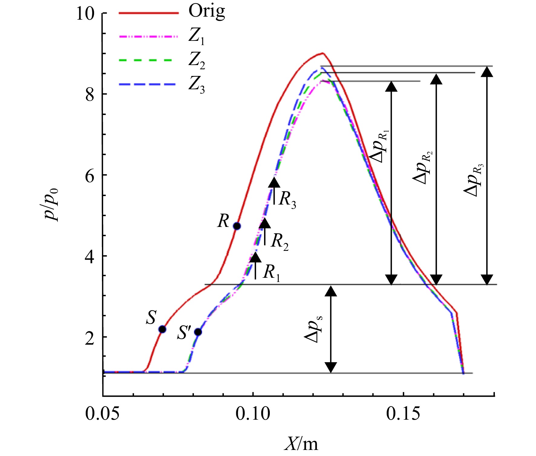
图17是基准模型与h=36 mm锯齿模型在不同参考线上静压比分布,图中锯齿模型的压比曲线整体低于基准模型,且分布相较后移,分离点S' 滞后于S,基准模型的再附点为R,h=36 mm锯齿模型 Z1、Z2、Z3线上再附点分别为
R1、R2、R3 。图中各曲线具有相同的初始压升Δps ,模型流动符合自由干扰理论[21]:分离起始阶段边界层受到的压升Δps 、干扰初始长度只与干扰起始点边界层的流动参数有关,不受入射激波强度的影响。锯齿模型各参考线上,分离跨度Z3>Z2>Z1 ,即越靠近两侧分离跨度越大;同时线上再附压升ΔpR3>ΔpR2>ΔpR1 ,再附点压比R3>R2>R1 。边界层受到的总压升为分离的初始压升Δps 与再附的第2次压升Δpr 之和,各模型初始压升Δps 相等,再附压升大,则要求再附过程开始时气流从外部流场输运更多的动量,分离区长度随之增大,即分离的长度与再附压升大小呈正相关。表3给出了h=36 mm锯齿模型Z1、Z2、Z3线所在的X-Y平面
Z′1、Z′2、Z′3 上分离流线的最大马赫数Mamax,表中可以看出对称面处的分离流线上具有较大的Mamax,说明附近的主流速度更大,输送给剪切层的动量更多,中部Z′1 处分离流线上Mamax最小。表 3 h=36 mm锯齿模型各分离流线上最大马赫数Table 3. Maximum Mach number on separation streamlines of h=36 mm sawtooth model参考平面 Mamax Z′1 0.30 Z′2 0.36 Z′3 0.45 2.2 不同锯齿深度的影响研究
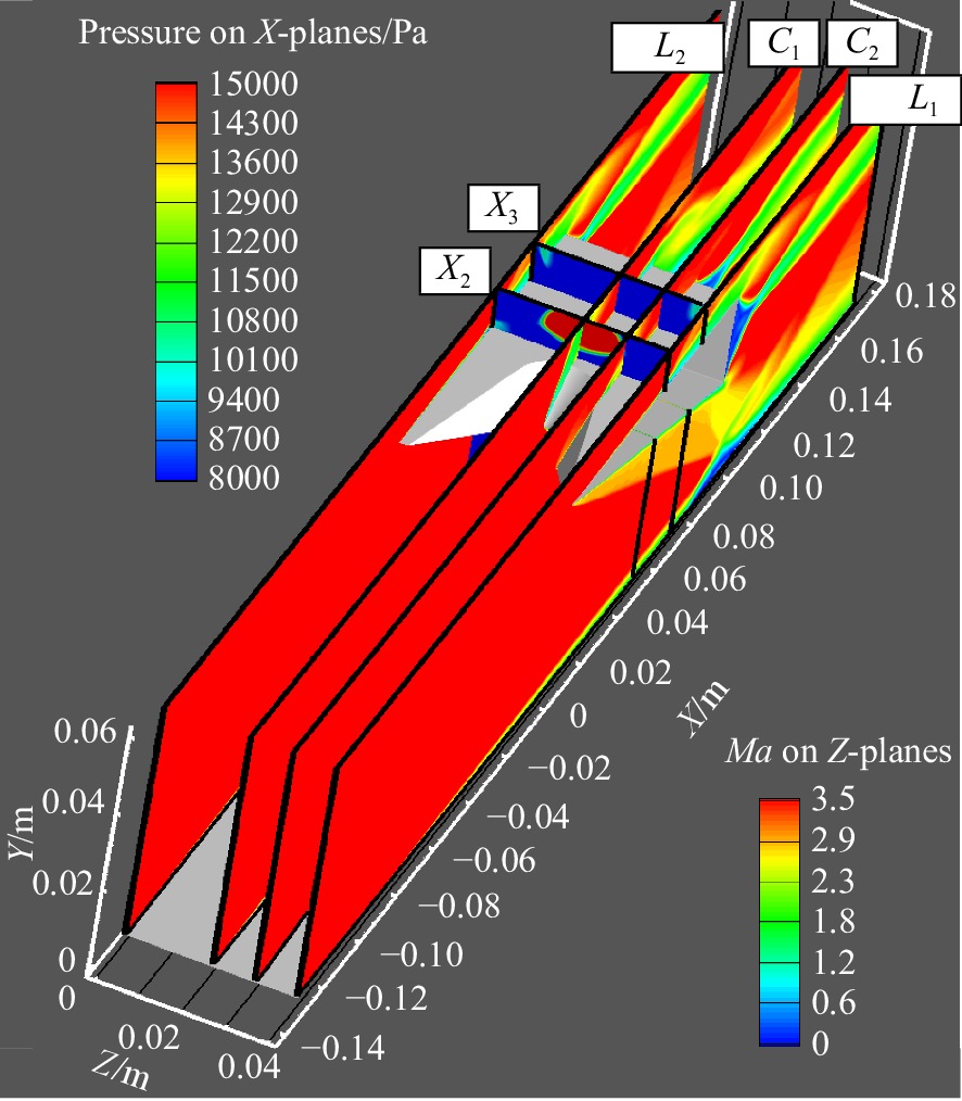
为研究锯齿深度对流场结构的影响,在其他参数不变的情况下对锯齿深度h=16,26,36 mm的锯齿模型开展研究。由于流场具有对称性,图18中以Z为法向在Z=20 mm处取参考面C1,Z=30 mm处取参考面C2,并提取参考面X2、X3上的静压分布以对比分析。
图19为不同锯齿深度h下的模型对称面L1和C1截面上马赫数分布云图,随着锯齿深度的不断增大,C1面上锯齿溢流增加,B激波弯曲加大,波后马赫数随之降低且流场分布更不均匀;L1处的前体激波入射到平板时的激波角随着锯齿深度的增大而有所减小,基准模型在L1截面下的激波角θ=27.4°,锯齿深度h=16 mm时激波角θ=25.8°,锯齿深度h=36 mm时激波角减小到24.2°。综合表现为整个三维曲面激波的强度随着锯齿深度的增大而有所减弱,因此由入射三维曲面激波产生的分离区分离线位置随着锯齿深度h的增大向下游推移。
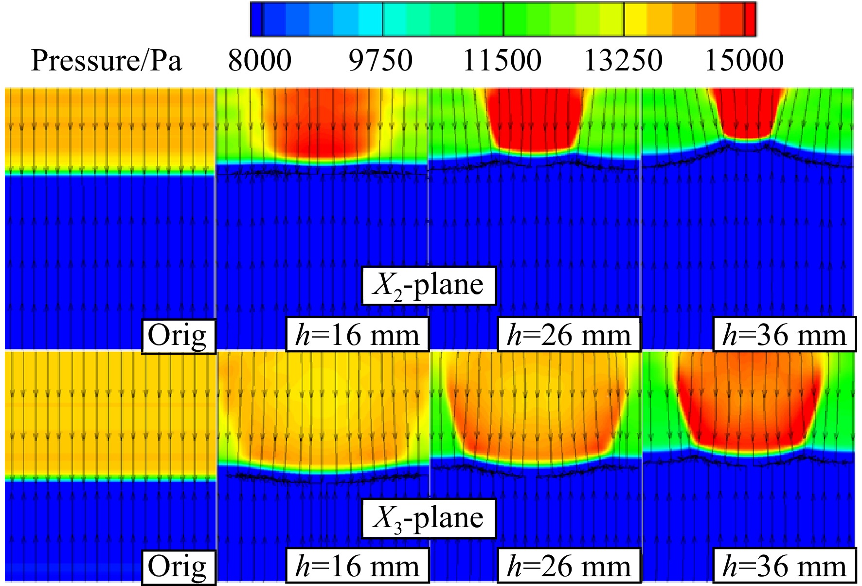
图20为4种模型在X2与X3参考面上的压力云图与流线分布。整体来看,B激波后压强高于两侧,往后发展的过程中影响范围扩大,激波强度减弱。随着锯齿深度增大,波角减小,波面位置上抬,B激波与两侧曲面激波间压差增大,流线向两侧低压区偏转趋势加强。
为分析底板回流区随锯齿深度h增加在流向上的变化情况,图21对比了各模型的底板表面极限流线分布和底板表面静压分布云图。从流线走向可以清晰观察到各模型底板上由分离线和再附线围成的带状回流区形状。各模型底板上回流区分离线均为平直,但随着锯齿深度h的增大,整体入射激波强度有所减弱,故分离线逐渐后移,分离区范围缩小。再附区的压强分布呈现出两侧增大中间减小的趋势,再附线更加弯曲,沿线的横向流动增强。
图22为基准模型与3种锯齿深度的锯齿模型在Z1线上的静压比分布曲线,平移各模型压比曲线使干扰起始点重合于点A。从图中可看出各模型压比变化的趋势相似,不同锯齿深度下分离区内从边界层干扰起始点A至压力平台P点的压升基本重合,即
Δps 不变,该初始压升区域为自由干扰区。锯齿模型的总压升均低于基准模型,且随着锯齿深度h的增大,再附压升Δpr 随之降低,各模型再附压升大小呈现为ΔpRorig>ΔpR16>ΔpR26>ΔpR36 ,即随着h的增大,底板分离区的中部逐渐缩小。由于各模型初始分离相同,这也意味着分离所引起的诱导激波强度一致,可粗略认为具有相同的诱导激波角度。当再附压升不同导致分离区长度不同时,在诱导激波角相同的前提下,分离包的高度随之相应受到影响:分离区长则对应的分离鼓包高度也高,分离区短则相反。为了支撑说明锯齿深度对流场影响的连续性与普适性,加入h=5.8, 8 mm两种小齿深的锯齿模型,并将5种锯齿模型与基准模型所产生流场的分离区参数进行比较,表4给出了基准模型与5种深度的锯齿模型产生的分离区在对称面L1、参考面C1上的高度和在底板上的跨度尺寸。在对称面上,锯齿模型的分离区高度和分离区跨度均略低于基准模型,受到再附压升与二次流动等因素的影响,锯齿模型分离区在对称面处变化不明显;在参考面C1上,分离高度和跨度均随h的增加有明显下降,因此锯齿模型的分离区在空间高度上呈现“凹”型,分离鼓包的背风区呈现与流向相反的“凹”型结构,且随着锯齿深度的增大,分离区展向和流向上的“凹”型趋势越明显。
表 4 各模型分离区在平面上特征尺寸Table 4. Characteristic size of separation zone on plane of different models模型 分离高度/mm 分离跨度/mm L1 C1 L1 C1 Orig 3.91 3.91 28.60 28.60 h=5.8 mm 3.83 3.63 28.25 27.16 h=8 mm 3.81 3.53 27.72 26.30 h=16 mm 3.81 3.38 27.46 24.60 h=26 mm 3.80 2.86 27.43 23.16 h=36 mm 3.79 2.62 27.43 21.00 2.3 溢流模型流场分析
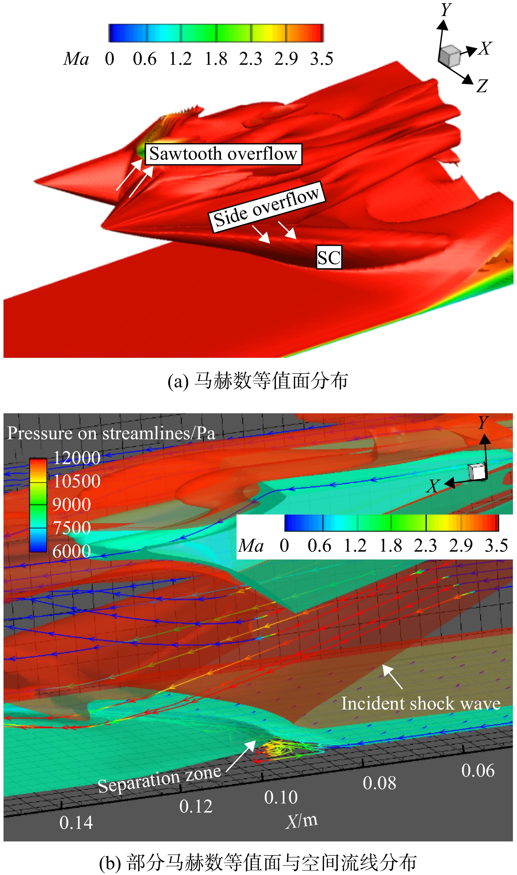
图23(a)为齿深h=26 mm的锯齿溢流模型在来流下所产生流场的马赫数等值面分布,部分气流通过锯齿溢出形成锯齿溢流(STOF);由于边缘效应[21]斜楔侧缘形成曲面激波
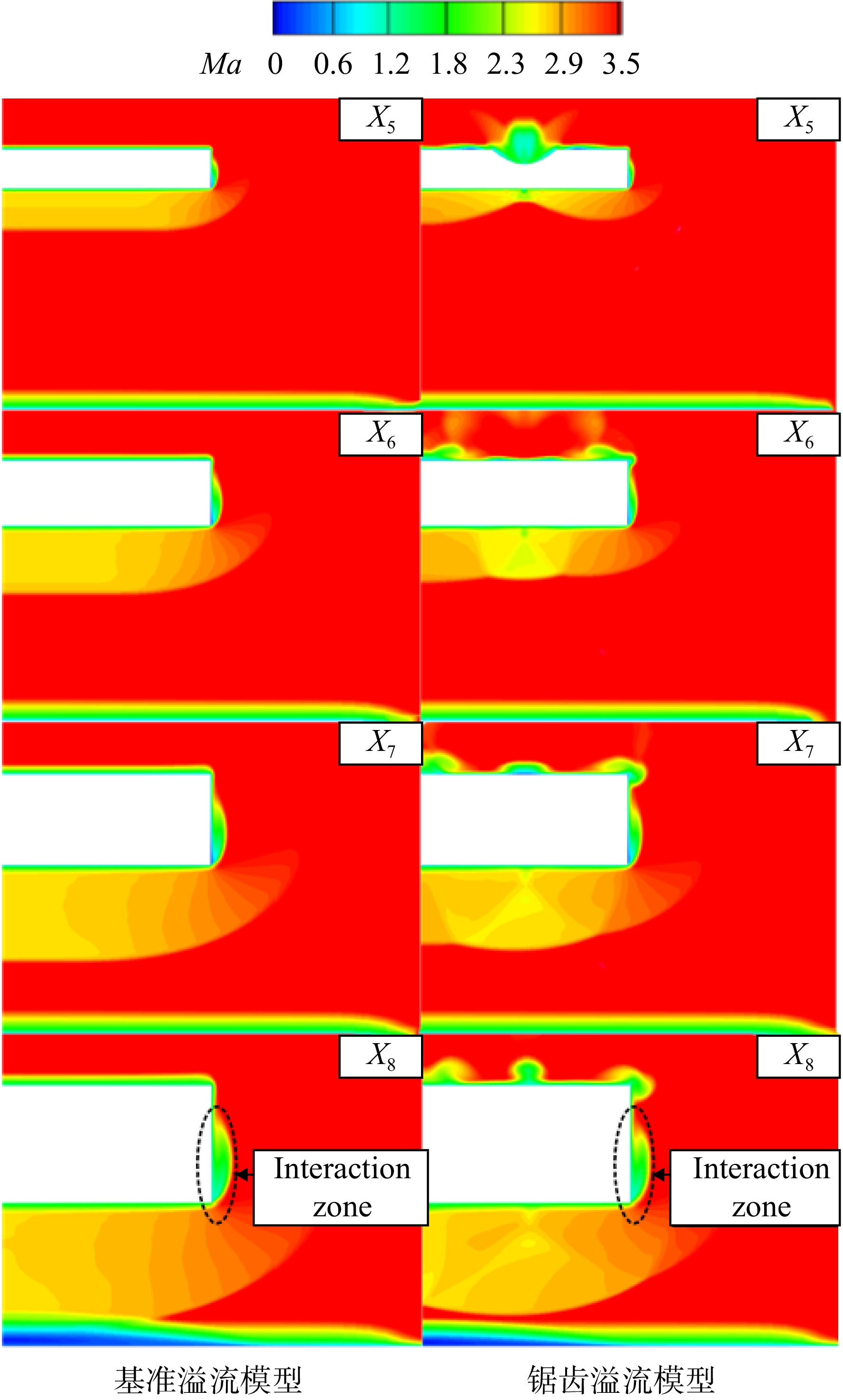
SC ,斜楔下方受入压缩后的高压气流在压差作用下向侧面溢出形成侧面溢流(SOF)。图23(b)为锯齿溢流模型流场中不同高度上的流线与线上静压分布,观察到侧面弯曲激波SC 波后气流静压较低,斜楔下方的高压流线向侧面偏转;底板上的分离区域呈现为不对称的“半凹”型结构,对称面处的分离范围仍最大,具有明显的回流;受侧面溢流的影响,靠近主流分离强度减弱,分离范围减小,回流消失,空间流线方向与主流方向一致。图24为基准溢流模型与锯齿深度为26 mm的锯齿溢流模型中X为法向的参考面X5(X=30 mm)、X6(X=50 mm)、X7(X=70 mm)与X8(X=90 mm)上马赫数分布云图。斜楔下方激波强度较高,在压差作用下部分气流侧流到斜楔侧面并与壁面边界层掺混形成小范围干扰区,靠近主流处激波强度减弱。在X5上,波后低速高压区域较小,侧向溢流量较少,干扰区范围小;随着X增大,波后高压区扩大,侧面溢流量增多,干扰区域增大。与无限宽锯齿模型相似,锯齿溢流模型入射激波仍为三波面形状,且入射波角小于基准溢流模型;各平面上锯齿溢流模型的干扰区域均小于基准溢流模型。
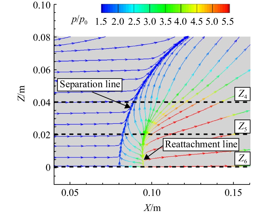
表5为无限宽度基准模型、无限宽度26 mm深锯齿模型与基准溢流模型、26 mm深锯齿溢流模型在溢流窗口上的溢流量。各模型来流条件相同,位于上游的锯齿溢流几乎不受下游影响,而锯齿使入射激波强度降低,波后气流与主流压差减小,使得锯齿溢流模型的侧面溢流要少于基准溢流模型。
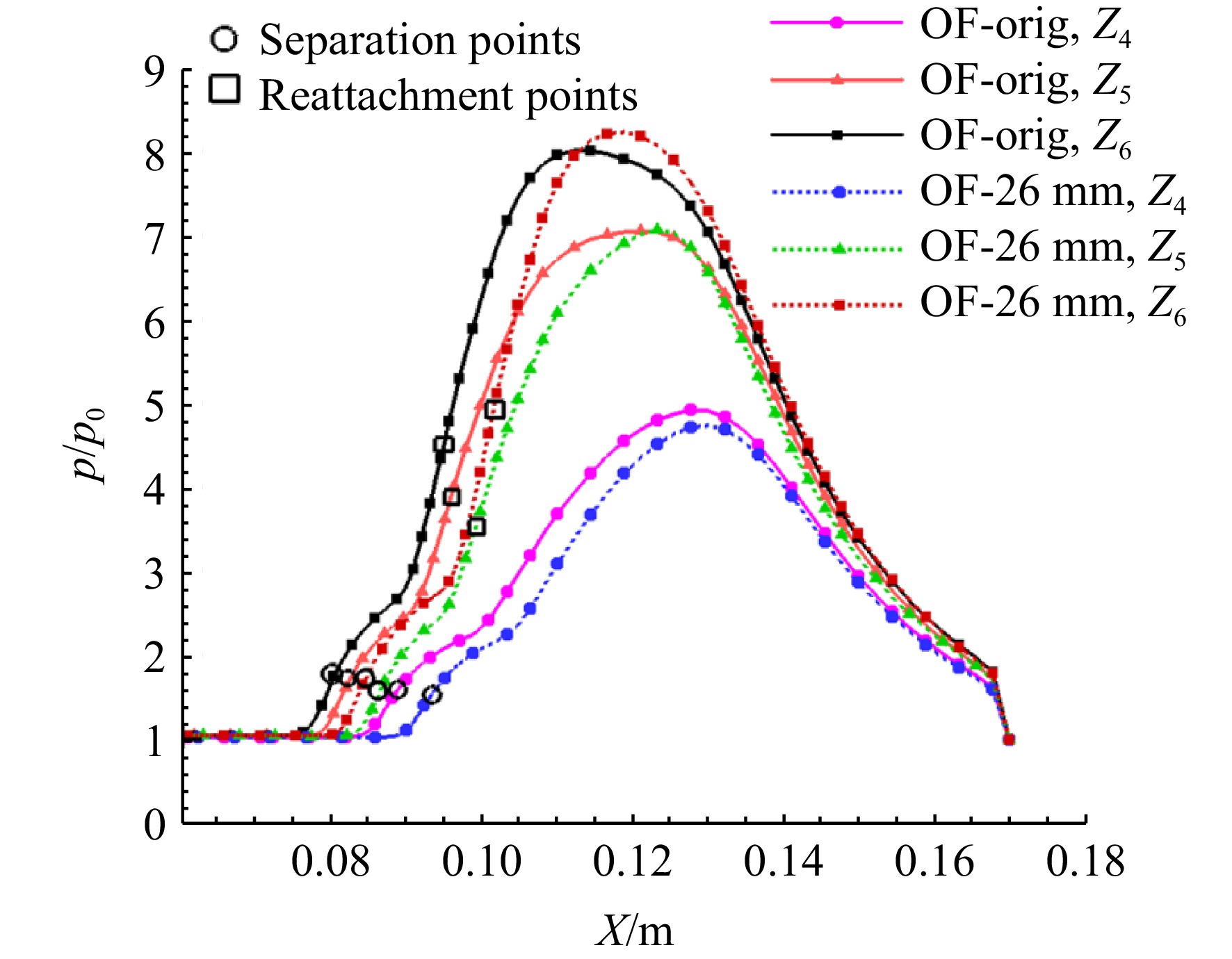
表 5 各模型溢流量Table 5. Overflow rate of models模型 质量流速/(kg/s) STOF SOF Orig h=26 mm 0.0105 OF-orig 0.0158 OF-26 mm 0.0105 0.0119 图25为基准溢流模型底板表面极限流线与线上静压比分布。从极限流线分布观察到,侧面溢流使分离线发生弯曲,再附线靠近主流处发散,回流消失;分离下游的再附区靠近对称面的压比最高,远离对称面处,侧面溢流削弱了入射激波强度,再附区压比减弱。从流动角度来看,楔块下方气流向侧面溢出,无黏区的侧向流动影响底板低能流动区域,分离区被破坏,主流侧的回流减弱并消失。在底板上选取参考线Z6(Z=0 mm)、Z5(Z=20 mm)和Z4(Z=40 mm)用于沿线静压分析。
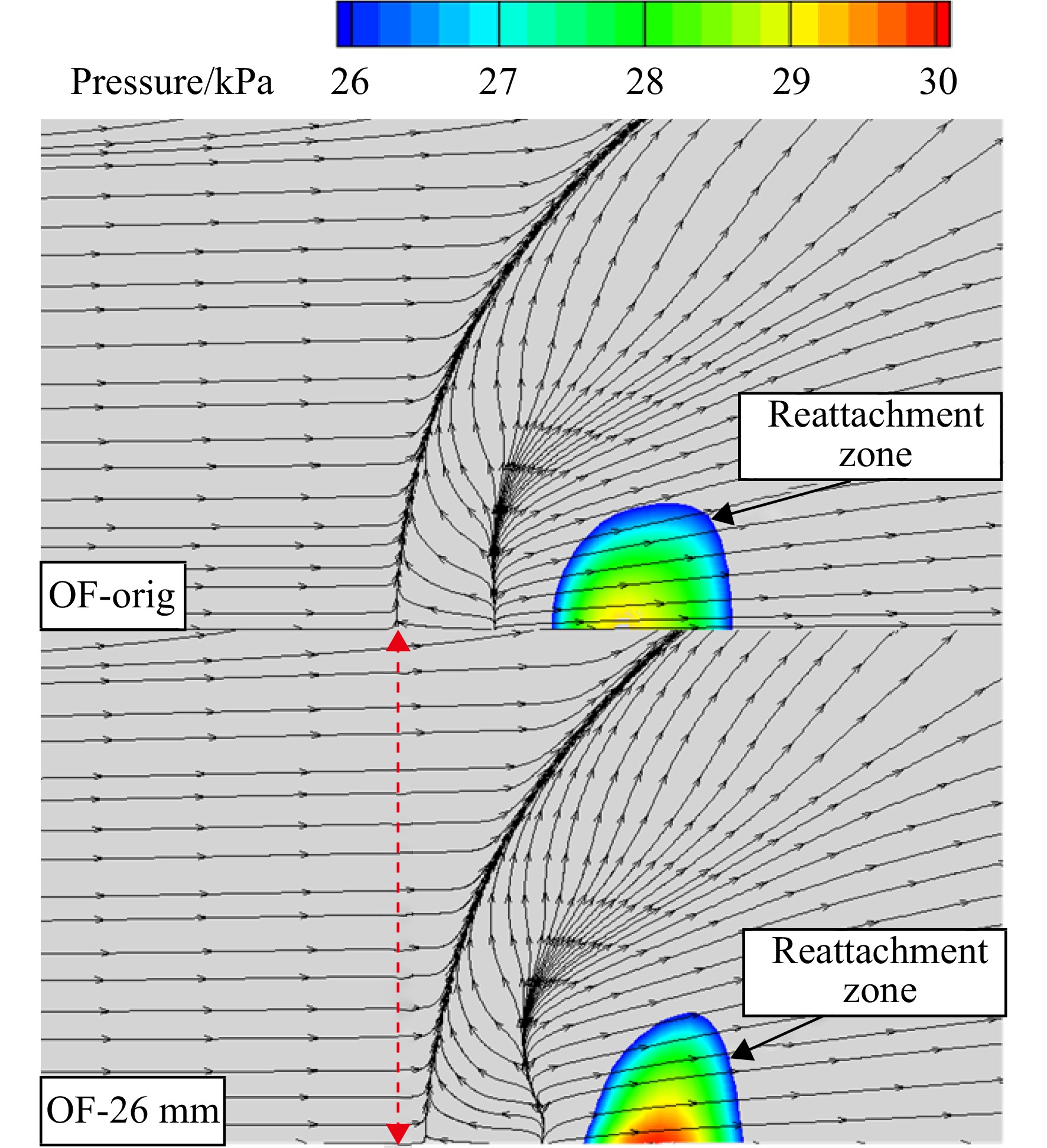
图26为基准溢流模型与h=26 mm锯齿溢流模型底板再附区静压云图与极限流线分布对比。由于锯齿溢流模型再附区内部压力分布不均,对称面处压强较大,故回流区在近对称面处跨度较大,再附线弯曲;而基准溢流模型再附区较为均匀且整体压强较低,再附线平直,回流跨度较小。两个模型的最大分离跨度均在对称面处,且锯齿溢流模型较大,这与锯齿溢流模型整体波系强度较基准溢流模型低,横向流动弱有关。
图27给出了基准溢流模型、h=26 mm锯齿溢流模型在Z4、Z5、Z6线上的压比分布曲线。由于溢流模型存在横向溢流,当地边界层流动状态在展向变化,自由干扰理论不再适用。各参考线上两种模型的起始压升均为
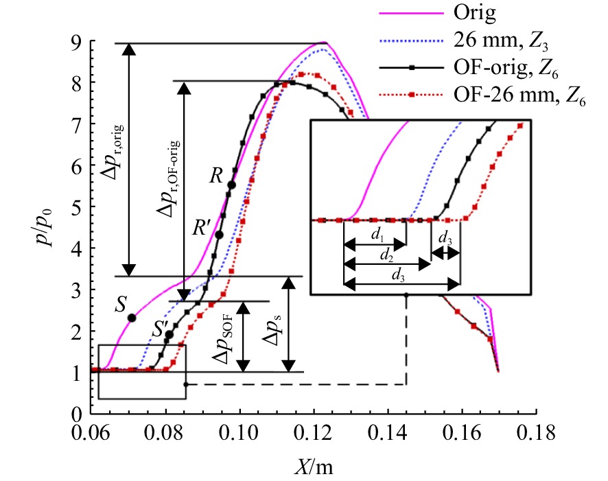
Δps6>Δps5>Δps4 ,说明分离诱导激波强度仍是对称面最强,沿着横向诱导激波强度减弱。锯齿溢流模型的再附压升随Z增大减小速率大于基准溢流模型,即基准溢流模型再附区内部压力梯度较小,锯齿溢流模型的分离区结构沿横向变化更明显。由对称面参考线Z6对比可以看出,锯齿溢流模型的再附压升大于基准溢流模型的,故其分离区跨度也较大。图28为无限宽度模型Z3参考线与溢流模型Z6参考线上压比曲线对比。边界层内流动状态差异使得溢流模型初始压升
ΔpSOF 小于无限宽度模型Δps ;受侧面溢流影响,基准溢流模型分离点S′ 滞后于基准模型分离点S,再附点R'位于基准模型的再附点R之前,总压升也低于无限宽度模型。分离起始点是反映流场分布的主要依据之一,当各模型来流条件相同,分离起始点靠前表明入射波角大、波系强度高,
d1、d2、d3、d4 为各模型参考线上起始压升点间距,由于各模型来流条件相同而流场特性不同。以无限宽度基准模型为基础流场,推得d1 为锯齿溢流对入射波系影响效果,d2 为侧面溢流影响效果,d3 为锯齿溢流与侧面溢流的综合影响效果,d4 为锯齿溢流对溢流基准模型入射波系影响效果。基准溢流模型的侧面溢流多于锯齿溢流,则d2 长度大于d1 ,而两种溢流对入射波系影响并非简单叠加,且d3<d1+d2 ;并且在相同的锯齿深度下,锯齿对入射激波强度的影响在无限宽度模型上影响明显大于溢流模型的,即d4<d1 ,主要是因为侧面溢流与入射波系强度间存在耦合关系,且对再附压升的影响较大。3. 结 论
本文通过数值仿真研究了前缘带锯齿的斜楔/底板结构下激波/边界层干扰的流场结构,分析了前缘不同锯齿深度斜楔对流场的影响规律,还综合分析了锯齿溢流与侧面溢流对模型入射激波/边界层干扰所产生的影响,结果表明:
1) 对比无限宽度的基准模型与锯齿模型的流场结构,发现基准模型入射激波为平面激波,斜楔前缘锯齿会使入射激波强度减弱,波角减小,入射激波面为三维曲面结构,由两侧强度变弱的曲面激波和中部强度较高的“桥”激波组成。
2) 无限宽基准模型和锯齿模型所引起的分离均符合自由干扰理论。基准模型的分离区呈现规则的二维结构,而锯齿模型由于其曲面入射激波结构使分离区下游再附区的再附压比分布不均,在高度方向上呈现中间低,两侧高,流向跨度上呈现中间短,两侧长的三维“凹”型结构。同时锯齿结构导致入射激波强度相对减弱,使激波/边界层引起的分离区整体后移,分离区域减小。
3) 对于无限宽的锯齿模型,随着锯齿深度h的增大,锯齿溢流量增多,入射激波强度降低,分离区进一步后移,分离区整体范围缩小,分离区内部二次流动加强,分离区凹型三维结构越明显,分流区的中间和两侧在高度和跨度上的差距进一步增大。
4) 溢流模型中锯齿的入射波系仍表现为三波系曲面结构,但受侧面溢流影响,侧面曲面激波弯曲程度加强;与无限宽锯齿模型相比,分离区对称结构被破坏,靠近对称面处分离呈“半凹”型。与基准溢流模型相比,锯齿溢流降低了入射波系强度,从而使侧面溢流减少,故在对称面处分离区跨度略大。
-
表 1 网格量设计
Table 1. Mesh quantity design
网格密度 网格量/104 粗网格 180 中等网格 380 密网格 500 表 2 流场参数
Table 2. Flow field parameters
Ma∞ p0/Pa T∞/K p*/Pa 3.8 3645 122.05 422415.1 表 3 h=36 mm锯齿模型各分离流线上最大马赫数
Table 3. Maximum Mach number on separation streamlines of h=36 mm sawtooth model
参考平面 Mamax Z′1 0.30 Z′2 0.36 Z′3 0.45 表 4 各模型分离区在平面上特征尺寸
Table 4. Characteristic size of separation zone on plane of different models
模型 分离高度/mm 分离跨度/mm L1 C1 L1 C1 Orig 3.91 3.91 28.60 28.60 h=5.8 mm 3.83 3.63 28.25 27.16 h=8 mm 3.81 3.53 27.72 26.30 h=16 mm 3.81 3.38 27.46 24.60 h=26 mm 3.80 2.86 27.43 23.16 h=36 mm 3.79 2.62 27.43 21.00 表 5 各模型溢流量
Table 5. Overflow rate of models
模型 质量流速/(kg/s) STOF SOF Orig h=26 mm 0.0105 OF-orig 0.0158 OF-26 mm 0.0105 0.0119 -
[1] BABINSKY H, HARVEY J K. Introduction[M]//BABINSKY H, HARVEY J K. Shock wave-boundary-layer interactions. Cambridge: Cambridge University Press, 2011: 1-4. [2] 黄舶. 高超声速内外流动激波/边界层相互作用的实验与数值研究[D]. 合肥: 中国科学技术大学, 2013.HUANG Bo. Experimental and numerical investigation of shock wave/boundary layer interaction in hypersonic flow[D]. Hefei: University of Science and Technology of China, 2013. (in Chinese) [3] ANDERSON G Y, MCCLINTON C R, WERDNER J P. Scramjet performance[M]. Reston, US: AIAA, 2000: 369-446. [4] DOLLING D S. Fifty years of shock-wave/boundary-layer interaction research-What next?[J]. AIAA Journal,2001,39(8): 1517-1531. doi: 10.2514/2.1476 [5] GAITONDE D V. Progress in shock wave/boundary layer interactions[J]. Progress in Aerospace Sciences,2015,72(1): 80-99. [6] SCHÜLEIN E. Skin friction and heat flux measurements in shock/boundary layer interaction flows[J]. AIAA Journal,2006,44(8): 1732-1741. doi: 10.2514/1.15110 [7] KORKEGI R H. A simple correlation for incipient-turbulent boundary-layer separation due to a skewed shock wave[J]. AIAA Journal,1973,11(11): 1578-1579. doi: 10.2514/3.50637 [8] MURRAY N,HILLIER R,WILLIAMS S. Experimental investigation of axisymmetric hypersonic shock-wave/turbulent-boundary-layer interactions[J]. Journal of Fluid Mechanics,2013,714: 152-189. doi: 10.1017/jfm.2012.464 [9] CLEMENS N T,NARAYANASWAMY V. Low-frequency unsteadiness of shock wave/turbulent boundary layer interactions[J]. Annual Review of Fluid Mechanics,2014,46: 469-492. doi: 10.1146/annurev-fluid-010313-141346 [10] 袁化成, 华正旭, 余安远. 高超声速进气道起动的物理过程及影响因素研究[C]//全国激波与激波管学术会议论文集. 洛阳: 中国力学学会激波与激波管委员会, 2016: 523-530. [11] BISEK N J. High-fidelity simulations of the HIFiRE-6 flow path at angle of attack[R]. AIAA 2016-4276, 2016. [12] STEELANT J, VARVILL R, DEFOORT S, et al. Achievements obtained for sustained hypersonic flight within the LAPCAT project[R]. AIAA 2015-3677, 2015. [13] 王翼. 高超声速进气道启动问题研究[D]. 长沙: 国防科学技术大学, 2008.WANG Yi. Investigation on the starting characteristics of hypersonic inlet[D]. Changsha: National University of Defense Technology, 2008. (in Chinese) [14] 石磊,何国强,秦飞,等. 唇口形状对二元进气道性能影响数值模拟[J]. 推进技术,2012,33(5): 683-688. doi: 10.13675/j.cnki.tjjs.2012.05.002SHI Lei,HE Guoqiang,QIN Fei,et al. Numerical investigation of effects of cowl lip shape on 2-D inlet[J]. Journal of Propulsion Technology,2012,33(5): 683-688. (in Chinese) doi: 10.13675/j.cnki.tjjs.2012.05.002 [15] 郭金默,谢旅荣,李晓驰,等. 一种锯齿状唇口超声速轴对称进气道特性[J]. 航空动力学报,2021,36(2): 264-274. doi: 10.13224/j.cnki.jasp.2021.02.005GUO Jinmo,XIE Lyurong,LI Xiaochi,et al. Characteristics of a supersonic axisymmetric inlet with saw tooth lip[J]. Journal of Aerospace Power,2021,36(2): 264-274. (in Chinese) doi: 10.13224/j.cnki.jasp.2021.02.005 [16] 金志光,张堃元. 高超侧压式进气道简单唇口调节方案设计[J]. 推进技术,2008,29(1): 43-48. doi: 10.3321/j.issn:1001-4055.2008.01.010JIN Zhiguang,ZHANG Kunyuan. Concept of a varied geometry scramjet inlet with rotatable cowl[J]. Journal of Propulsion Technology,2008,29(1): 43-48. (in Chinese) doi: 10.3321/j.issn:1001-4055.2008.01.010 [17] XIAO Fengshou,LI Zhufei,ZHANG Zhiyu,et al. Hypersonic shock wave interactions on a V-shaped blunt leading edge[J]. AIAA Journal,2018,56(1): 356-367. doi: 10.2514/1.J055915 [18] 蒙泽威,范晓樯,陶渊,等. 三维内收缩式进气道V形溢流口热流计算与分析[J]. 推进技术,2018,39(8): 1737-1743. doi: 10.13675/j.cnki.tjjs.2018.08.007MENG Zewei,FAN Xiaoqiang,TAO Yuan,et al. Investigation of aerothermal heating on V-shaped leading edge of inward turning inlet[J]. Journal of Propulsion Technology,2018,39(8): 1737-1743. (in Chinese) doi: 10.13675/j.cnki.tjjs.2018.08.007 [19] 张恩来,李祝飞,李一鸣,等. 斜激波入射V形钝前缘溢流口激波干扰研究[J]. 实验流体力学,2018,32(3): 50-57. doi: 10.11729/syltlx20180002ZHANG Enlai,LI Zhufei,LI Yiming,et al. Investigation on the shock interactions between an incident shock and a plate with V-shaped blunt leading edge[J]. Journal of Experiments in Fluid Mechanics,2018,32(3): 50-57. (in Chinese) doi: 10.11729/syltlx20180002 [20] LI Yiming, LI Zhufei, YANG Jiming, et al. Visualization of hypersonic inward-turning inlet flows by planar laser scattering method[R]. AIAA 2017-2358, 2017. [21] BABINSKY H, HARVEY J. Shock wave-boundary-layer interactions[M]. Cambridge, UK: Cambridge University Press, 2011. -


 下载:
下载:


 下载:
下载:
