






Modeling method and cycle analysis of high-speed gas turbine engine with CCA technology
-
摘要:
针对高马赫数涡轮发动机的涡轮部件热防护问题,以基于冷气预冷(CCA)技术的变循环涡扇(VCTF)发动机为例,建立燃油的热物性库,换热器、涡轮叶片冷却以及改进燃烧室的计算模型,发展VCTF发动机的设计点迭代计算模型,分析CCA技术对VCTF发动机循环性能的影响。结果表明:CCA技术能够在相同涡轮材料耐温的水平下进一步增大发动机净推力,但是耐高温涡轮叶片材料的应用仍是提升发动机的性能的关键。对于未采用耐高温涡轮叶片材料的低压涡轮(LPT),其导向器和转子的冷气量随着高压涡轮(HPT)材料耐温的水平提高而增大;采用CCA技术后,低压涡轮导向器的冷气量减少,但是未采用预冷引气的低压涡轮转子的冷气量进一步增大,耐高温涡轮叶片材料的应用能够明显降低这一不利影响。
-
关键词:
- 高马赫数涡轮发动机 /
- 冷气预冷(CCA)技术 /
- 建模方法 /
- 设计点迭代 /
- 循环性能
Abstract:For the thermal protection of turbine components of high-speed gas turbine engines, a variable cycle turbofan (VCTF) engine with cooled cooling air (CCA) technology was taken as an example. The library of fuel thermal physical property, and the simulation model of the heat exchanger, the turbine blade cooling, and the combustion chamber with fuel temperature change were established. The iteration simulation model of design point for the high-speed VCTF engine was developed, and the influence on the thermodynamic cycle performance of the VCTF engine with CCA technology was analyzed. Results showed that at the same turbine temperature limits level, the CCA technology can further increase the thrust of the high-speed gas turbine engine. However, the application of high-temperature resistant material into turbine blades was still the key to improving the performance of the high-speed gas turbine engine. For the low-pressure turbine (LPT) without high-temperature resistant material, the relative cooling air bleeds of the LPT stator and rotor increased with the increase of high-pressure turbine (HPT) temperature limits level; after the CCA technology was adopted, the relative cooling air bleed of the LPT stator decreased, and that of the LPT rotor without cooled cooling air further increased. Applying high-temperature resistant material into LPT can reduce this adverse effect.
-

图 1 基于CCA技术的VCTF发动机结构示意图
Figure 1. Schematic diagram of VCTF engine structure with CCA technology
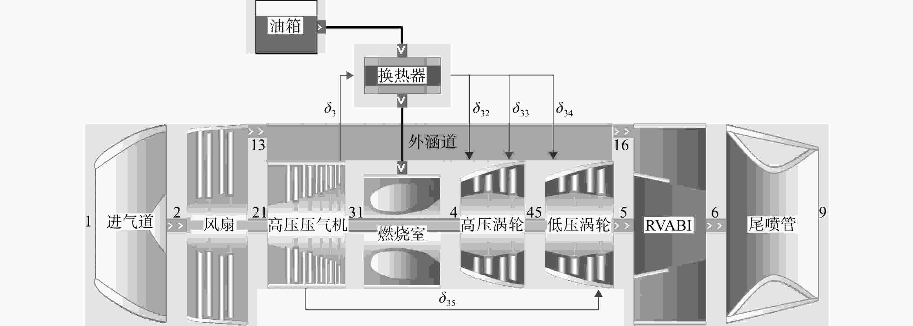
图 2 基于CCA技术的VCTF发动机性能仿真模型
Figure 2. Simulation model for the VCTF engine performance with CCA technology

图 3 3 MPa下RP-3的热物性参数对比
Figure 3. Thermophysical parameters comparison of RP-3 at 3 MPa
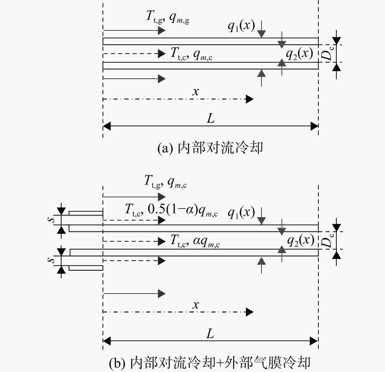
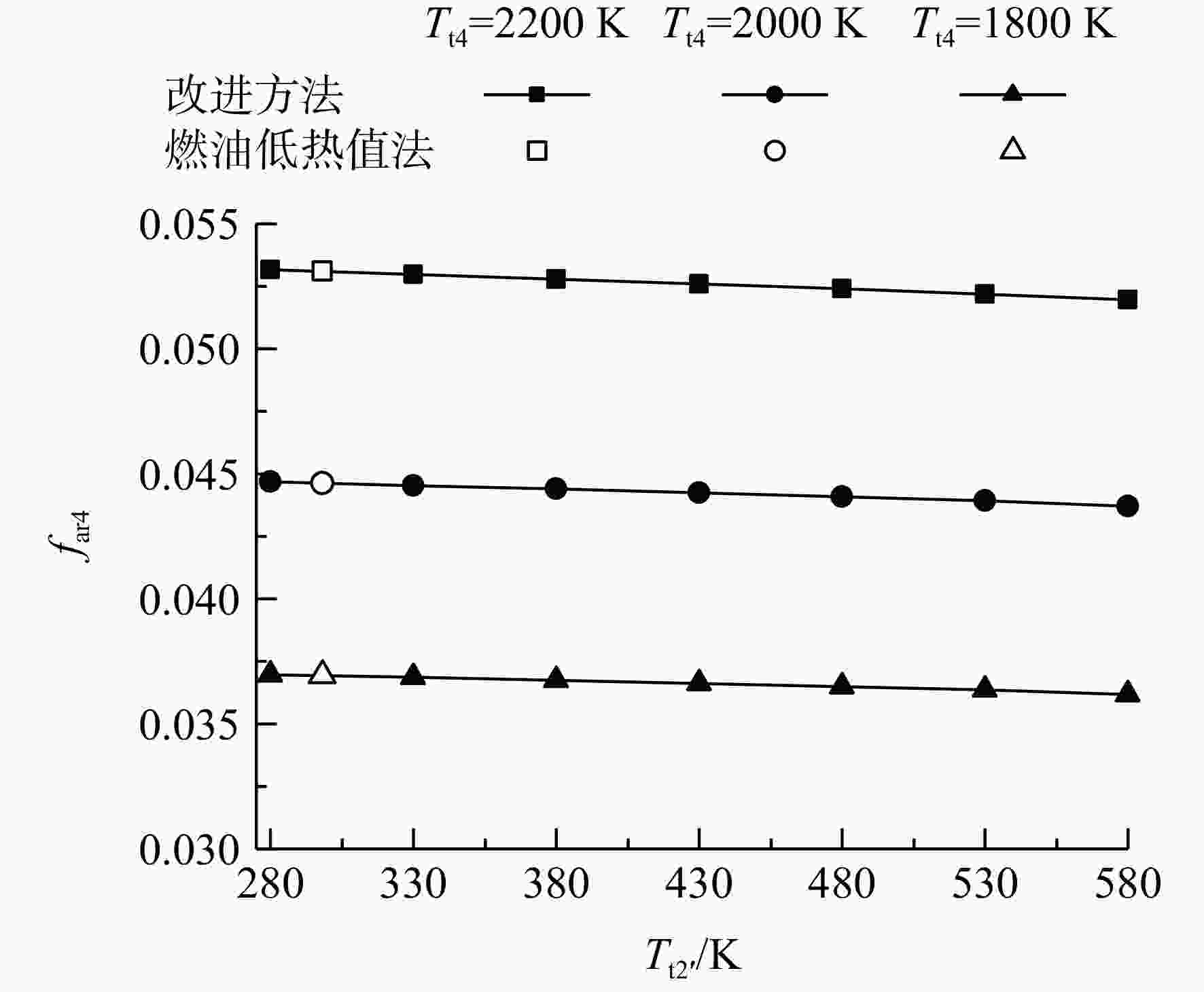
图 5 不同燃烧室出口总温下油气比随燃油温度变化
Figure 5. Variation of fuel-air ratio vs initial fuel temperature at different burner exit total temperature
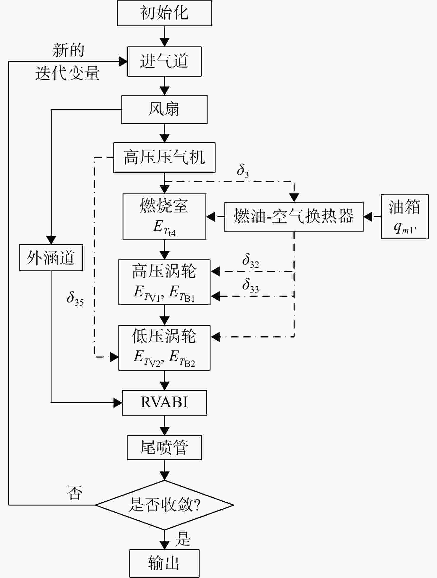
图 6 基于CCA技术的VCTF发动机的设计点迭代计算流程
Figure 6. Design point iterative calculation procedure of the VCTF engine with CCA technology
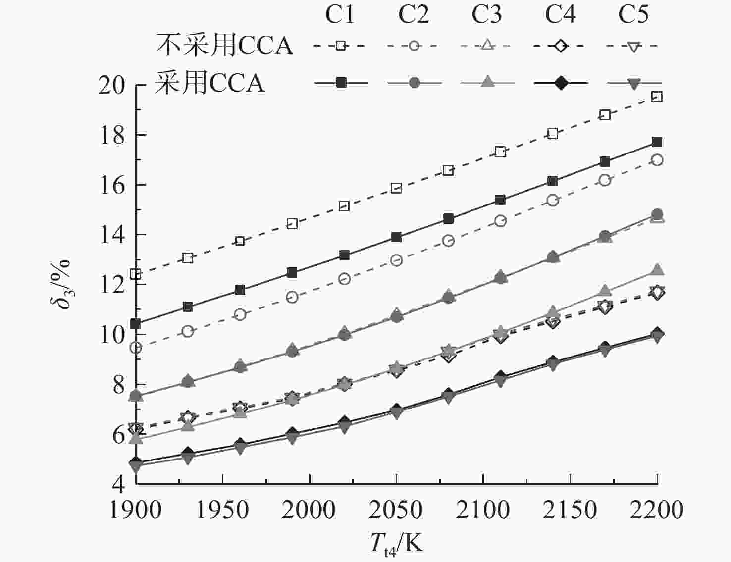
图 7 不同涡轮前温度和涡轮叶片温度的限制水平下高压压气机出口的相对引气量
Figure 7. Relative bleeding air flow from HPC exit vs turbine inlet temperature and turbine blade temperature limits
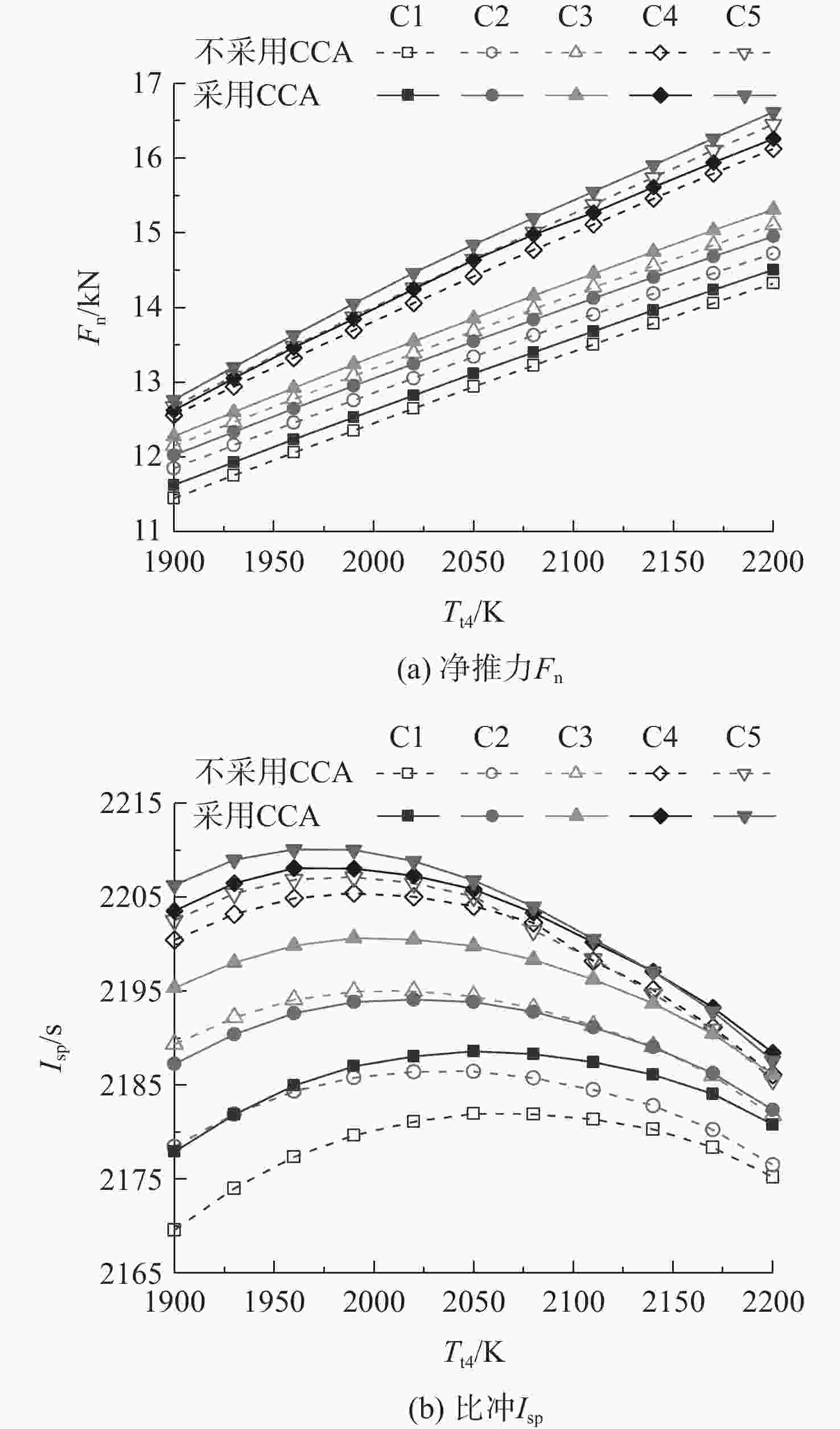
图 8 不同涡轮前温度和涡轮叶片温度的限制水平下VCTF发动机总体性能
Figure 8. Overall performance of the VCTF engine vs turbine inlet temperature and turbine blade temperature limits
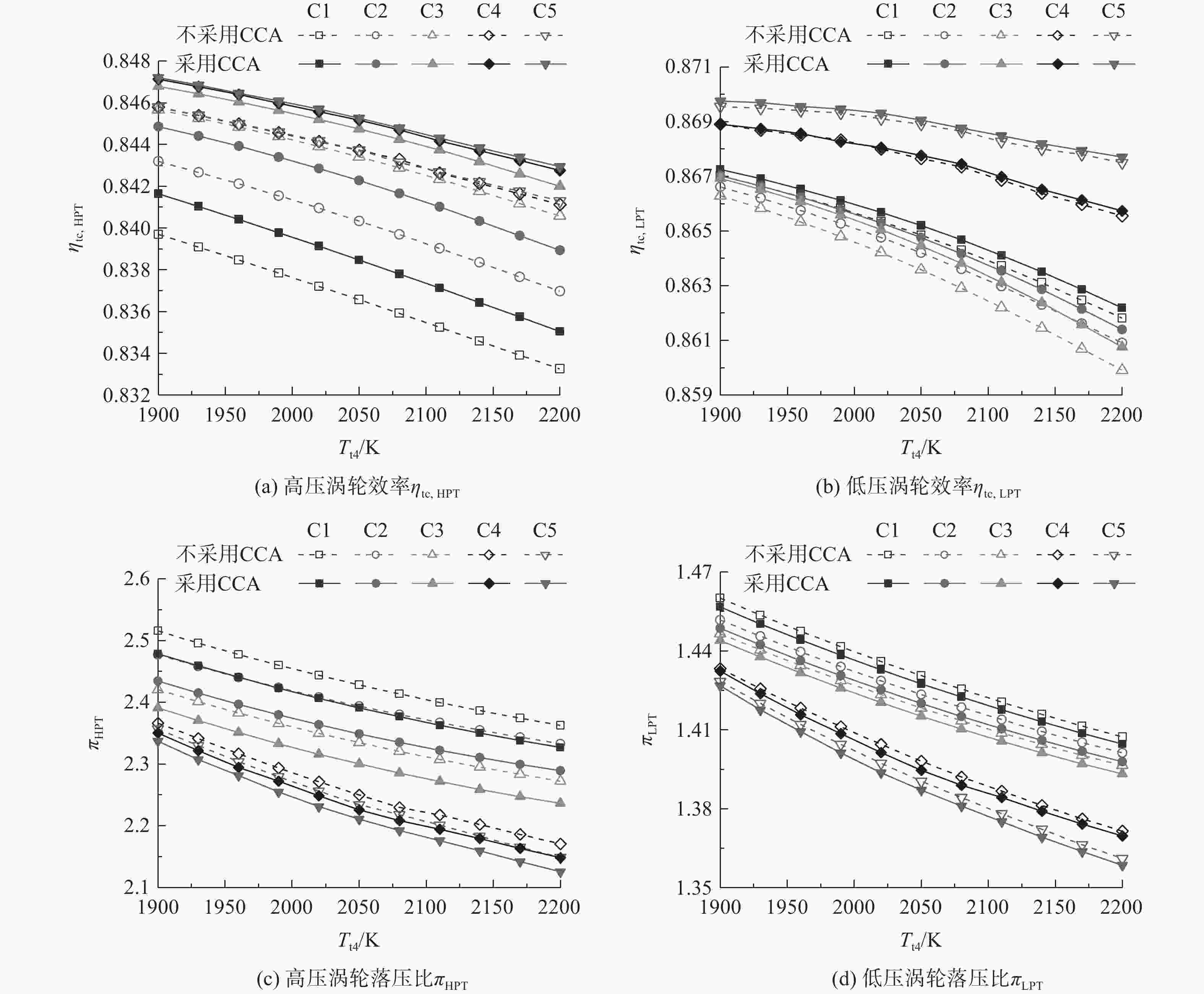
图 9 不同涡轮前温度和涡轮叶片温度的限制水平下高、低压涡轮的性能参数变化规律
Figure 9. Performance parameters of HPT and LPT vs. turbine inlet temperature and turbine blade temperature limits
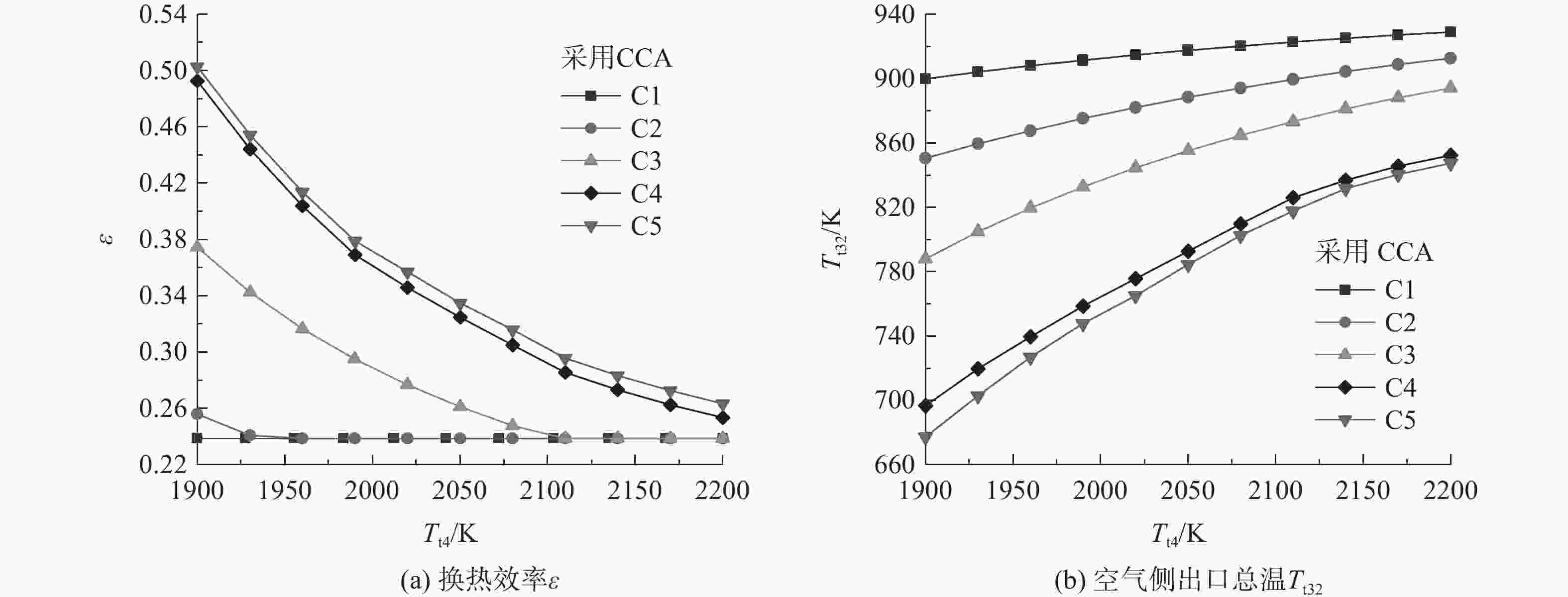
图 10 不同涡轮前温度和涡轮叶片温度的限制水平下燃油-空气换热器的循环参数变化规律
Figure 10. Cycle parameters of fuel-air heat exchanger vs. turbine inlet temperature and turbine blade temperature limits
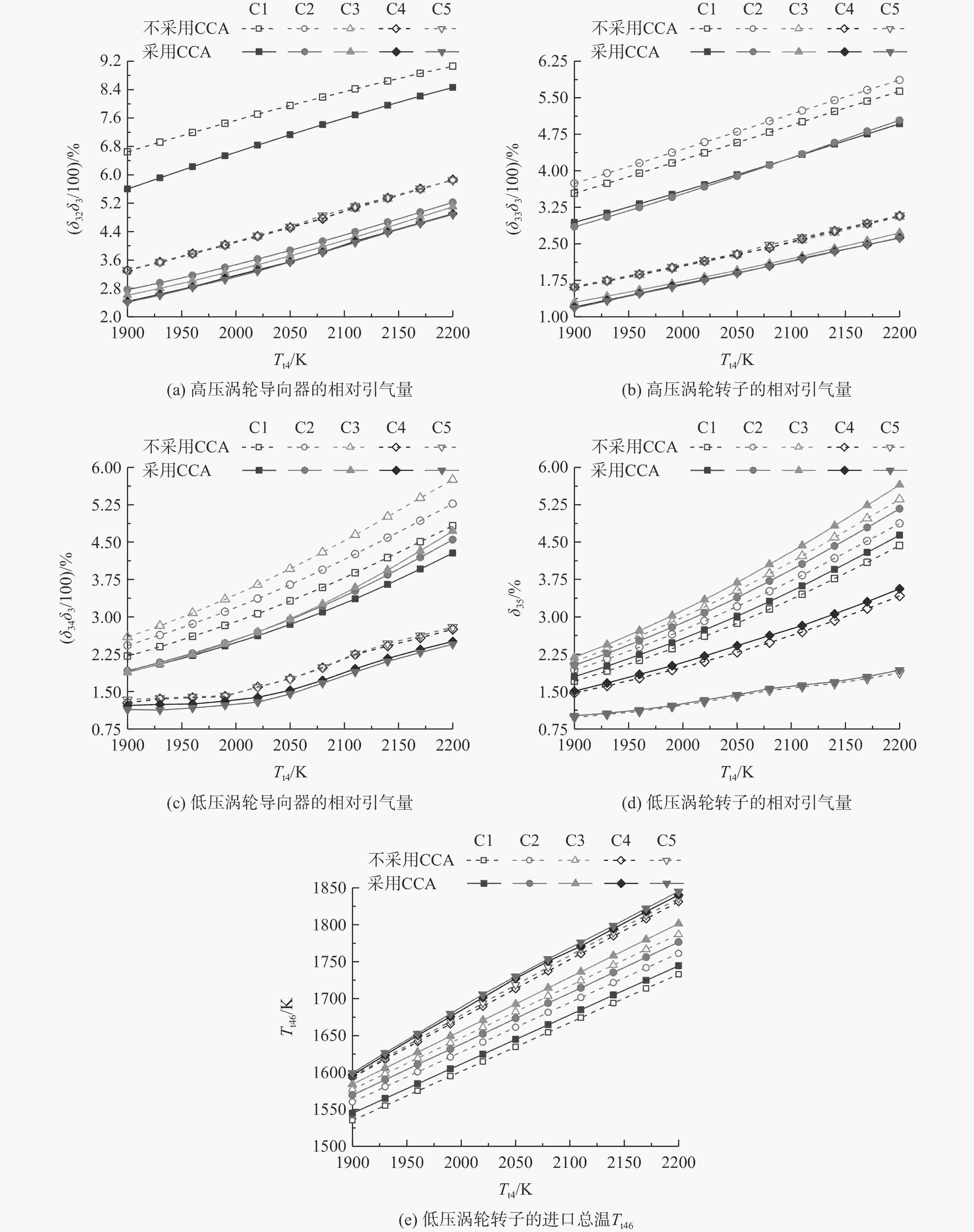
图 11 不同涡轮前温度和涡轮叶片温度的限制水平下高、低压涡轮的循环参数变化
Figure 11. Cycle parameters of HPT and LPT vs. turbine inlet temperature and turbine blade temperature limits
冷却方式 对流冷却
相对流量α级效率损失 导向器
(rV1/rV2)转子
(rB1/rB2)先进对流 1.0 0.1 0.2 对流和气膜 1 0.75 0.12 0.24 对流和气膜2 0.50 0.15 0.30 对流和气膜3 0.25 0.18 0.36 全气膜 0 0.35 0.60  下载: 导出CSV
表 2 基于CCA技术的VCTF发动机基准设计参数和总体性能参数
Table 2. Baseline design and overall performance parameters of the VCTF engine with CCA technology
基准设计参数 数值 发动机进口空气流量/(kg/s) 41 进气道总压恢复系数 0.80 风扇压比 1.40 风扇涵道比 0.94 高压压气机压比 3.60 高压压气机出口总温/K 992.0 燃油箱出口温度/K 380 燃油箱出口压力/MPa 2.6 燃油-空气换热器
总压恢复系数空气 0.97 燃油 0.89 燃油-空气换热器进口相对引气量δ3/% 10.43 燃油-空气换热器燃油侧出口总温/K 526 燃油-空气换热器空气侧出口总温/K 895 燃油-空气换热器换热效率 0.238 燃烧室出口总温Tt4/K 1900 燃烧室总压恢复系数 0.95 高压涡轮 导向器相对引气量δ32/% 57 转子相对引气量δ33/% 29 导向器叶片限制温度TV1/K 1338 转子叶片限制温度TB1/K 1338 修正前(后)等熵效率 0.85 (0.842) 低压涡轮 导向器相对引气量δ34/% 14 转子相对引气量δ35/% 1.64 导向器叶片限制温度TV2/K 1338 转子叶片限制温度TB2/K 1230 修正前(后)等熵效率 0.87 (0.867) 净推力Fn/kN 11.63 比冲Isp/s 2177
下载: 导出CSV
表 3 涡轮叶片冷却计算的输入参数
Table 3. Input parameters for turbine blade cooling calculation
叶片参数 高压涡轮 低压涡轮 导向器 转子 导向器 转子 Mac 0.3 0.3 0.35 0.3 弦长/m 0.036 0.045 0.058 0.068 叶距/m 0.034 0.028 0.048 0.037 叶高/m 0.036 0.045 0.058 0.068 叶片数 42 51 36 47 α 0.5 0.5 0.5 0.5
下载: 导出CSV
表 4 半经验方法与一维方法计算结果对比
Table 4. Calculation result comparison between semi-empirical method and one-dimensional method
方法 计算参数 导向器 转子 一维方法 冷却流因子 0.0312 0.0413 对流冷却效率 0.632 0.653 气膜冷却效率 0.313 0.308 相对引气量/% 29.00 1.64 半经验方法 相对引气量/% 29.52 1.69
下载: 导出CSV
表 5 循环性能分析选取的不同参数技术水平
Table 5. Selection of different parameters technology levels for cycle performance analysis
参数 方案编号 C1 C2 C3 C4 C5 Tt4/K 1900~2200 TV1/K 1338 1530 1530 1530 1530 TB1/K 1338 1338 1530 1530 1530 TV2/K 1338 1338 1338 1530 1530 TB2/K 1230 1230 1230 1338 1530
下载: 导出CSV
表 6 不采用CCA技术下涡轮材料耐温的水平依次提高对净推力的提升
Table 6. Net thrust improvement by increasing turbine material temperature resistant level without CCA technology
方案 净推力提升百分比/% C1 C2 2.80~3.52 C3 2.52~2.60 C4 3.41~6.72 C5 0.90~2.07
下载: 导出CSV
表 7 相同涡轮材料耐温的水平下采用CCA技术对净推力的提升
Table 7. Net thrust improvement with CCA technology under same turbine material temperature resistant level
方案 净推力提升百分比/% C1 1.26~1.54 C2 1.47~1.56 C3 1.06~1.37 C4 0.5~1.49 C5 0.69~1.40
下载: 导出CSV
-
[1] 王占学,张明阳,张晓博,等. 变循环涡扇冲压组合发动机发展现状及关键技术分析[J]. 推进技术,2020,41(9): 1921-1934. doi: 10.13675/j.cnki.tjjs.200321WANG Zhanxue,ZHANG Mingyang,ZHANG Xiaobo,et al. Development status and key technologies of variable cycle turbofan-ramjet engine[J]. Journal of Propulsion Technology,2020,41(9): 1921-1934. (in Chinese) doi: 10.13675/j.cnki.tjjs.200321 [2] MARLEY C D, DRISCOLL J F. Modeling an active and passive thermal protection system for a hypersonic vehicle[R]. AIAA 2017-0118, 2017. [3] MURTHY N B, CURRAN E T. Developments in high-speed vehicle propulsion systems[M]. Blacksburg, US: AIAA Press, 1996. [4] STEPKA F S. Considerations of turbine cooling systems for Mach 3 flight[R]. NASA/TN-1968-D-4491, 1968. [5] BERGHOLZ F R, HITCH B D. Thermal management systems for high Mach airbreathing propulsion[R]. AIAA-92-0515, 1992. [6] RUED K, EBENHOCH G, MARK H. Thermal management of propulsion systems in hypersonic vehicles[R]. AIAA-92-0516, 1992 [7] KISHI K, KUNO N, KASHIWAGI T, et al. Exhaust nozzle research in Japanese HYPR program[R]. AIAA-95-2606, 1995. [8] KISHI K,JOUBERT H. Research of 2-D variable exhaust nozzle[J]. International Journal of Gas Turbine, Propulsion and Power Systems,2013,5(1): 17-22. doi: 10.38036/jgpp.5.1_17 [9] BARTOLOTTA P A, MCNELIS N B, SHAFER D G. High speed turbines: development of a turbine accelerator (RTA) for space access[R]. AIAA 2003-6943, 2003. [10] BRUENING G B, CHANG W S. Cooled cooling air systems for turbine thermal management[R]. ASME 99-GT-014, 1999. [11] SNYDER E L, ESCHER D W. Turbine based combination cycle (TBCC) propulsion subsystem integration[R]. AIAA 2004-3649, 2004. [12] GAMBLE E J, HAID D A, D’ALESSANDRO S, et al. Dual-mode scramjet performance model for TBCC simulation[R]. AIAA 2009-5298, 2009. [13] GAMBLE E J, HAID D A. Thermal management and fuel system model for TBCC dynamic simulation[R]. AIAA 2010-6642, 2010. [14] LOU D C,GUO W,WANG Z G,et al. Integrated thermal management system design for advanced propulsion system[J]. Applied Mechanics and Materials,2012,232: 723-729. doi: 10.4028/www.scientific.net/AMM.232.723 [15] 刘友宏,李甲珊,唐世建,等. 涡轮冲压组合发动机燃油系统温升仿真研究[J]. 推进技术,2020,41(5): 984-991. doi: 10.13675/j.cnki.tjjs.180594LIU Youhong,LI Jiashan,TANG Shijian,et al. Simulation of fuel system temperature rise in turbine based combined cycle engine[J]. Journal of Propulsion Technology,2020,41(5): 984-991. (in Chinese) doi: 10.13675/j.cnki.tjjs.180594 [16] ITAHARA H, KOHARA S, TAKAGI S, et al. Turbo engine research in Japanese HYPR project for HST combined cycle engine[R]. AIAA-94-3358, 1994. [17] HERRING N R. On the development of compact, high performance heat exchangers for gas turbine applications[D]. West Lafayette, US: Purdue University, 2007. [18] 沙拉, 塞库利克. 换热器设计技术[M]. 程林, 译. 北京: 机械工业出版社, 2010. [19] 张明阳,王占学,张晓博,等. 串联式TBCC发动机风车冲压模态性能模拟[J]. 航空动力学报,2018,33(12): 2939-2949. doi: 10.13224/j.cnki.jasp.2018.12.014ZHANG Mingyang,WANG Zhanxue,ZHANG Xiaobo,et al. Simulation of windmilling-ram mode performance for tandem TBCC engine[J]. Journal of Aerospace Power,2018,33(12): 2939-2949. (in Chinese) doi: 10.13224/j.cnki.jasp.2018.12.014 [20] ZHONG F,FAN X,YU G,et al. Heat transfer of aviation kerosene at supercritical conditions[J]. Journal of Thermophysics and Heat Transfer,2009,23(3): 543-550. doi: 10.2514/1.41619 [21] HUBER M L. NIST thermophysical properties of hydrocarbon mixtures database (SUPERTRAPP)[M]. Gaithersburg, US: National Institute of Standards and Technology, 2003. [22] DENG H W,ZHU K,XU G Q,et al. Isobaric specific heat capacity measurement for kerosene RP-3 in the near-critical and supercritical regions[J]. Journal of Chemical and Engineering Data,2011,57(2): 263-268. [23] DENG H W,ZHANG C B,XU G Q,et al. Density measurements of endothermic hydrocarbon fuel at sub- and supercritical conditions[J]. Journal of Chemical and Engineering Data,2011,56(6): 2980-2986. doi: 10.1021/je200258g [24] GAUNTNER J W. Algorithm for calculating turbine cooling glow and the resulting decrease in turbine efficiency[R]. NASA/TM-1980-81453, 1980. [25] SCHNEIDER S J. Analysis of turbine blade relative cooling flow factor used in the subroutine cool it based on film cooling correlations[R]. NASA/TM-2015-218738, 2015. [26] YOUNG J B,WILCOCK R C. Modeling the air-cooled gas turbine: Part 2 coolant flows and losses[J]. Journal of Turbomachinery,2002,124(2): 214-221. doi: 10.1115/1.1415038 [27] GORDON S, MCBRIDE B J. Computer program for calculation of complex chemical equilibrium compositions and applications[R]. NASA/RP-1994-1311, 1994. [28] MASER A C. Optimal allocation of thermodynamic irreversibility for the integrated design of propulsion and thermal management systems[D]. Atlanta, US: Georgia Institute of Technology, 2012. [29] 陈敏,唐海龙,朱大明,等. 高超声速串联式组合动力装置方案[J]. 北京航空航天大学学报,2007,33(3): 265-268. doi: 10.3969/j.issn.1001-5965.2007.03.004CHEN Min,TANG Hailong,ZHU Daming,et al. Hypersonic combined cycle engine concept with tandem layout[J]. Journal of Beijing University of Aeronautics and Astronautics,2007,33(3): 265-268. (in Chinese) doi: 10.3969/j.issn.1001-5965.2007.03.004 [30] 特尼格尔, 闻洁, 付衍琛, 等. 细管蛇形管换热器流动与换热特性实验研究[C]// 中国航天第三专业信息网第39届技术交流会暨第3届空天动力联合会议论文集: S05发动机热管理技术. 河南 洛阳: 中国空天动力联合会, 2018: 2-13. [31] GREGORY B T. Test results of the Northrop Grumman corporation turbine engine bleed air/fuel heat exchanger after 165 hours of operation with JP-8+100 fuel[R]. AIAA-98-5559, 1998. [32] 郑华雷,苏志敏,黄兴,等. 基于多设计点方法的陶瓷基材料涡桨发动机热力循环分析[J]. 推进技术,2021,42(1): 1-9. doi: 10.13675/j.cnki.tjjs.200183ZHENG Hualei,SU Zhimin,HUANG Xing,et al. Thermal cycle analysis of turboprop with ceramic matrix composite based on multiple design points approach[J]. Journal of Propulsion Technology,2021,42(1): 1-9. (in Chinese) doi: 10.13675/j.cnki.tjjs.200183 [33] MATTINGLY J D, HEISER W H, PRATT D T, et al. Aircraft engine design[M]. Blacksburg, US: AIAA Press, 2018. -


 点击查看大图

计量
- 文章访问数: 900
- HTML浏览量: 348
- PDF量: 118
- 被引次数: 0