


Design and validation of transonic nozzle guide vane profile of radial-inflow turbine
-
摘要:
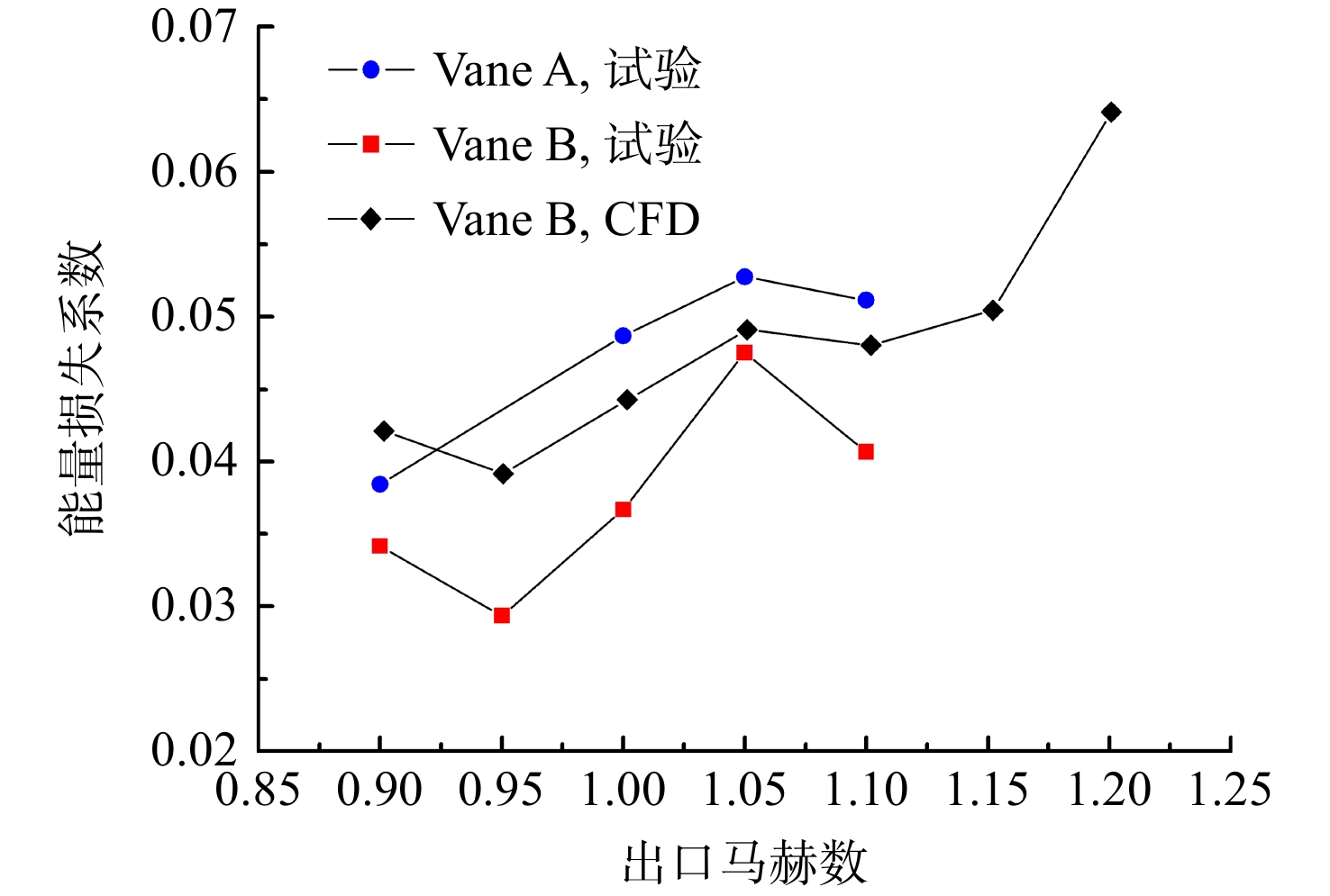
以某先进辅助动力装置用膨胀比5.0级向心涡轮跨声速导叶为研究对象,从消除几何喉部前局部超声区及削弱尾缘激波强度两方面着手,对导向叶片进行了优化改进及叶栅试验验证,结果表明:采用大正攻角、小安装角的设计思路,减小喉部前吸力面叶型曲率,降低进口段的通道面积,提高了叶型前段负荷,消除了喉部前的过膨胀区,喉部前气流加速更为均匀;在吸力面喉部后构建局部内凹结构,可将原方案中吸力面尾缘处一道较强的激波变为两道较弱的激波,峰值马赫数降低,尾缘逆压梯度减小,尾缘激波强度得以削弱。试验结果显示:在出口马赫数0.9~1.1范围内,优化后叶型能量损失系数均有所降低,在出口马赫数为1.1时,能量损失系数可降低近20%。
Abstract:Taking the transonic nozzle guide vane of a radial-inflow turbine with expansion ratio of 5.0 for an advanced auxiliary power unit as the research object, the vane profile was optimized and cascade tests were conducted by eliminating the local ultrasonic region in front of the throat and weakening the shock wave intensity at the trailing edge. The research showed that by adopting the design idea of large positive incidence angle and small installation angle, and reducing the curvature of suction side before the throat, reducing the flow area of inlet duct, the load in front of the blade profile was improved, the over expansion area before the throat was eliminated, and the airflow acceleration was more uniform. A local concave structure was constructed behind the throat of the suction surface, which can transform one strong shock wave at the trailing edge of the suction surface into two relatively weak shock waves. The peak Mach number decreased, and the adverse pressure gradient at the trailing edge decreased, weakening the strength of the trailing edge shock wave. The test results indicated that the energy loss coefficient of optimized profile dropped as the cascade exit Mach numbers varied from 0.9 to 1.1, and the energy loss coefficient dropped nearly 20% when the exit Mach number was 1.1.
-
Key words:
- radial-inflow turbine /
- transonic cascade /
- nozzle guide vane /
- profile design /
- shock loss
-

图 3 典型向心涡轮导叶叶型表面静压分布
Figure 3. Static pressure distribution of typical radial-inflowturbine nozzle guide vane

图 10 叶中截面出口周向损失对比
Figure 10. Loss distribution along circumferential direction at the exit of mid-span

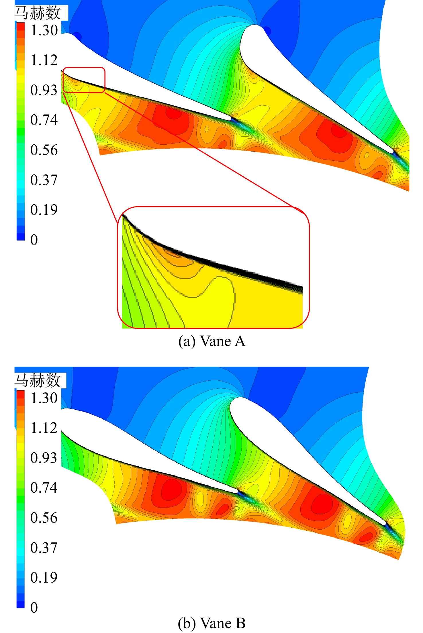
图 12 马赫数计算值与试验值对比
Figure 12. Comparison of calculated and tested Mach number distributions

图 13 计算与试验出口周向能量损失系数对比
Figure 13. Comparison of calculated and tested exit circumferential energy loss coefficient distributions

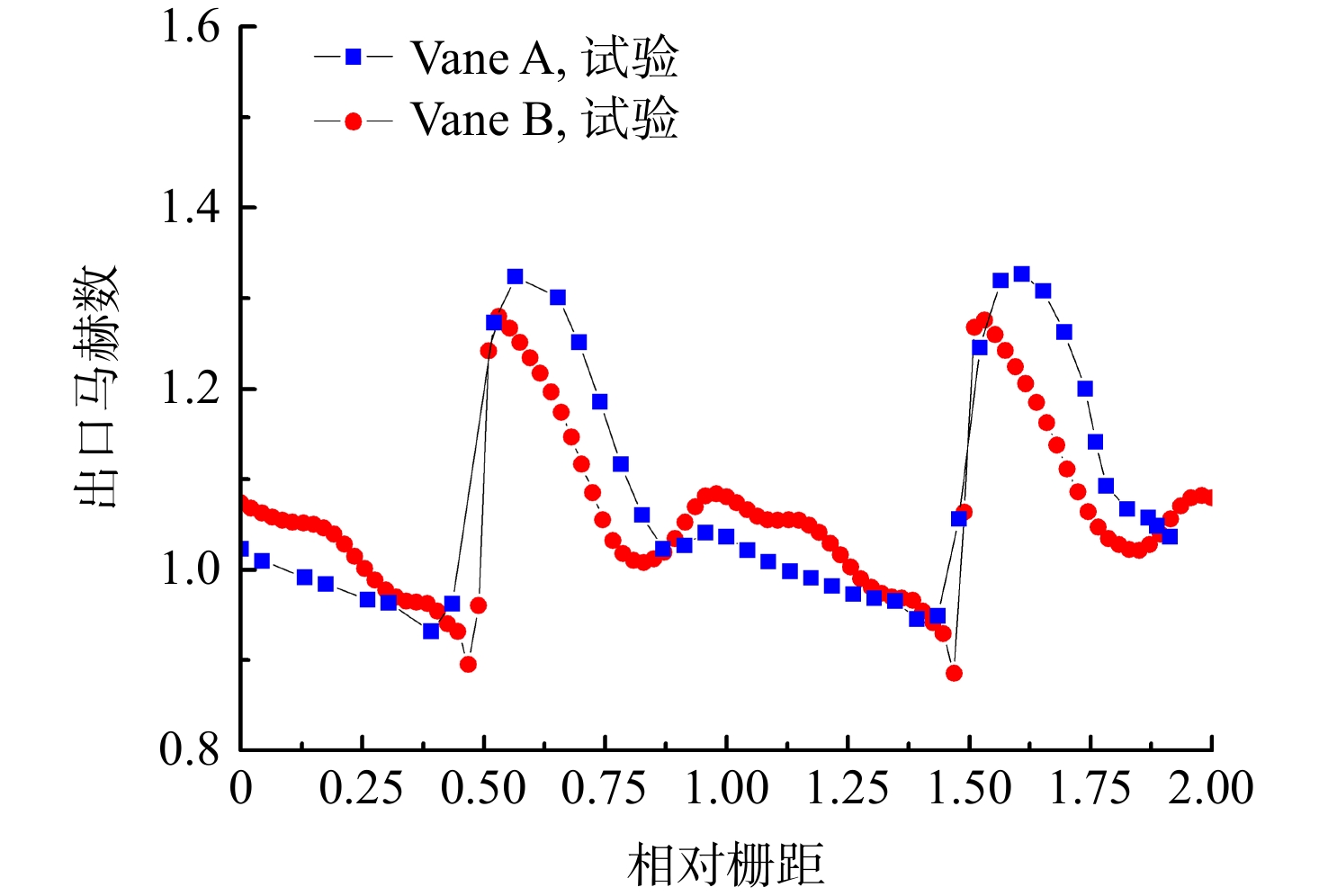
图 14 不同叶型周向出口马赫数试验结果对比
Figure 14. Comparison of tested exit circumferential Mach number with different profiles

图 15 能量损失系数随出口马赫数变化对比
Figure 15. Comparison of energy loss coefficient with different exit Mach number
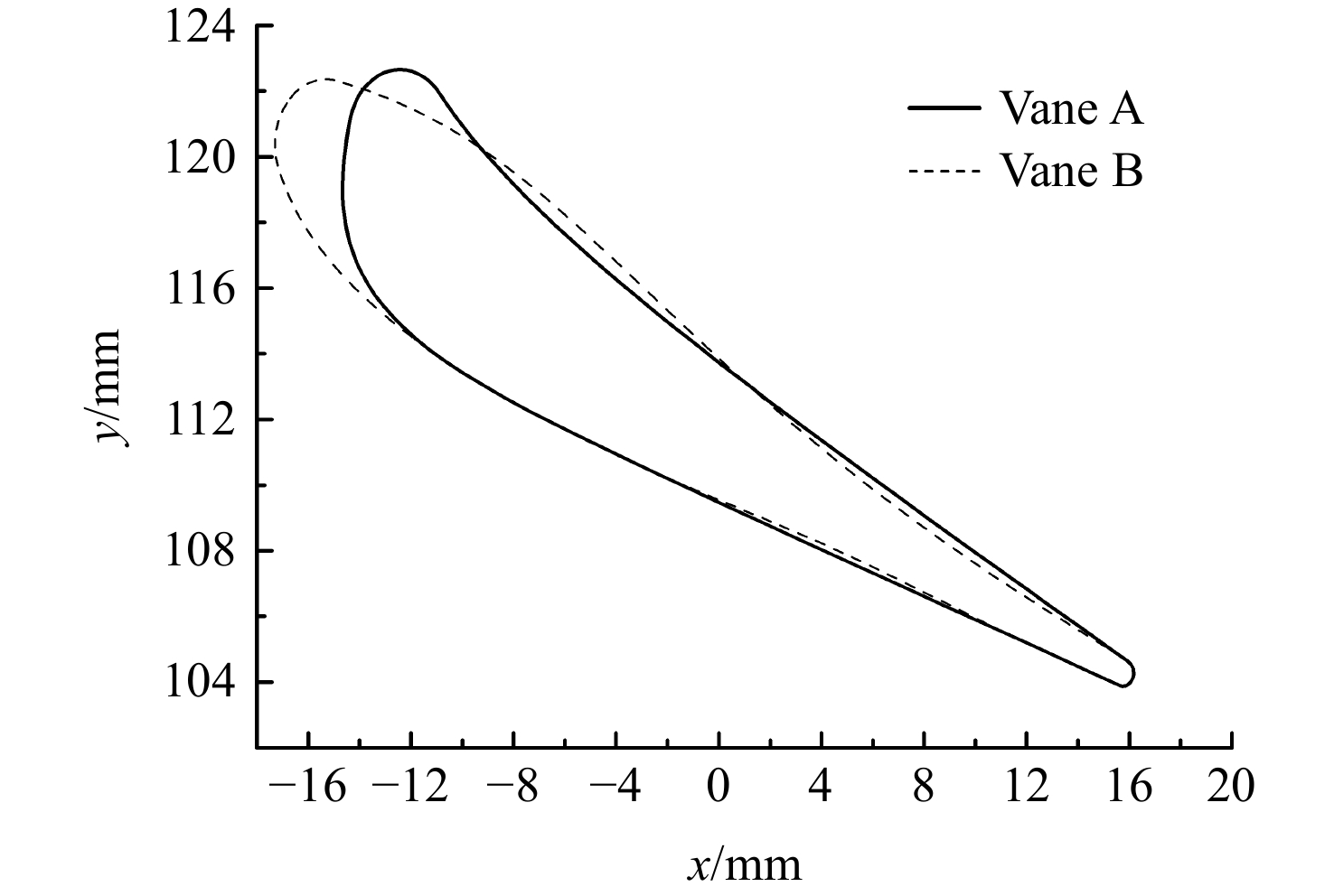
表 1 叶型几何参数
Table 1. Geometric parameters of profile
几何参数 Vane A Vane B 导叶叶片数 Nv 23 23 径向弦长 br/mm 19.0 19.0 尾缘半径 rt/mm 0.4 0.4 进口构造角 α1/(°) 90 135 出口构造角 α2/(°) 19 19 尾缘楔角 ω2/(°) 5.0 4.0 喉部收敛角αc/(°) 20.0 15.0 安装角 γ/(°) 33.0 29.0 喉宽o/mm 8.78 8.78 栅距s/mm 28.53 28.53  下载: 导出CSV
表 2 叶型损失系数对比
Table 2. Comparison of blade profile loss coefficient
损失系数 Vane A Vane B 附面层摩擦损失+
尾缘前激波损失系数0.01974 0.01655 尾迹损失+尾缘后激波损失系数 0.01553 0.01400 叶型总损失系数 0.05201 0.04861
下载: 导出CSV
-
[1] STOHLGREN L M, WERNER L D. The GTCP36-300, a gas turbine auxiliary power unit for advanced technology transport aircraft[R]. ASME Paper 86-GT-285, 1986. [2] MOHSEN M S, MOSTAFA O. Optimization of a high pressure ratio radial-inflow turbine: coupled CFD-FE analysis[R]. ASME Paper GT2015-42208, 2015. [3] AMIR K N,SHERVIN S. Detailed design and aerodynamic performance analysis of a radial-inflow turbine[J]. Applied Sciences,2018,8(11): 2207-2227. doi: 10.3390/app8112207 [4] JONES A C. Design and test of a small, high pressure ratio radial turbine[J]. Journal of Turbomachinery,1996,118(2): 362-370. doi: 10.1115/1.2836651 [5] DUAN P H,TAN C S,SCRIBNER A,et al. Loss generation in transonic turbine blading[J]. Journal of Turbomachinery,2018,140(4): 410-422. [6] CROW D E, VANCO M R, WELNA H, et al. Results from tests on a high work transonic turbine for an energy efficient engine[R]. ASME Paper GT-80-146, 1980. [7] GIEL P W. NASA/GE highly-loaded turbine research program[R]. New Orleans, US: NASA Fundamental Aeronautics 2007 Annual Meeting, 2008. [8] GRAHAM C G, KOST F H. Shock boundary layer interaction on high turning transonic turbine cascades[R]. ASME Paper 79-GT-37, 1979. [9] TSUJITA H, MIZUKI S, YAMAMOTO A. Numerical investigation of blade profile effects on aerodynamic performance of ultra-highly loaded turbine cascades[R]. ASME Paper GT2004-53429, 2004. [10] JOUINI D B M, SJOLANDER S A, MUSTAPHA S H. Aerodynamic performance of a transonic turbine cascade at off-design conditions[J]. ASME Paper 2000-GT-0482, 2000. [11] SONODA T. A study of advanced high-loaded transonic turbine airfoils[J]. Journal of Turbomachinery,2006,128(4): 650-657. doi: 10.1115/1.2221325 [12] HUEA H S, SAEIDI R, GIEL P, et al. Design and test results of a ultra high loaded single stage high pressure turbine[R]. ASME Paper GT-2013-94055, 2013. [13] ZHAO W, LUO W W, ZHAO Q J, et al. Investigation on the reduction of trailing edge shock losses for a highly loaded transonic turbine[R]. ASME Paper GT2016-56131, 2016. [14] ZHOU Q H,ZHAO W,SUI X M,et al. A shock loss reduction method using a concave suction side profile for a zero inlet swirl turbine rotor[J]. Journal of Turbomachinery,2022,144(11): 510-514. [15] REICHERT A W, SIMON H. Numerical investigations on the optimum design of radial inflow turbine guide vanes[R]. Hague, Netherlands: International Gas Turbine and Aeroengine Congress and Exposition, 1994. [16] REICHERT A W, SIMON H. Design and flow field calculations for transonic and supersonic radial inflow turbine guide vanes[R]. ASME Paper 95-GT-97, 1995. [17] PULLEN K R, BAINES N C, HILL S H. The design and evaluation of a high pressure ratio radial turbine[R]. ASME Paper 92-GT-93, 1992. [18] YANG D F, LAO D Z, YANG C, et al. Investigation on the generation and weakening of shock wave in a radial turbine with variable guide vanes[R]. ASME Paper GT2016-57047, 2016. [19] 张绍文,石建成,李维,等. 高负荷涡轮进口导向叶片叶型设计及验证[J]. 航空动力学报,2021,36(1): 185-192. doi: 10.13224/j.cnki.jasp.2021.01.021ZHANG Shaowen,SHI Jiancheng,LI Wei,et al. Design and validation of high-lift turbine nozzle guide vane profile[J]. Journal of Aerospace Power,2021,36(1): 185-192. (in Chinese) doi: 10.13224/j.cnki.jasp.2021.01.021 [20] PETR S. Calculation of transonic flow in radial turbine blade cascade[R]. AIP Conference Proceedings 1889 020041, 2017. -


 点击查看大图

计量
- 文章访问数: 126
- HTML浏览量: 37
- PDF量: 43
- 被引次数: 0