






Study on the mechanism of flow loss in the tip region of turbine rotors
-
摘要:
为详细研究涡轮转子叶尖区局部流动损失机理,应用内部脱体涡模拟程序对涡轮转子叶尖端区流动进行了脱体涡模拟,获得了高精度流场信息。通过熵产分析对叶尖端区泄漏流与主流掺混过程中的局部流动损失进行了定量评估,分辨和探究了时均流场和脉动流场对熵产率的贡献及贡献机制。研究结果表明:时均熵产和脉动熵产对涡轮转子动叶尖区流动损失的重要组成部分,上游由时均熵产主导,下游由脉动熵产主导。时均熵产的产生及其空间分布形式均由泄漏射流的法向速度型决定,上下游泄漏流法向速度型边界层厚度和剪切强度的差异,导致了时均熵产大小和空间形态的差异。脉动熵产的产生是由时均变形率张量引起的脉动熵产自放大项和脉动场旋涡结构引起的压力黑森项主导。
Abstract:An in-house detached eddy simulation program was employed to simulate the flow in the turbine rotor blade tip region, and high-precision flow field data were obtained, so as to comprehensively investigate the physical process of local aerodynamic loss in this region. The local mixing loss caused by mixing between tip leakage and mainstream flows in the tip clearance region was quantitatively assessed using entropy production analysis. Additionally, the mechanisms and contributions of the time-averaged flow field and fluctuating flow field to the entropy production rate were explored. The results demonstrated that both time-averaged and fluctuating entropy productions were important sources of the mixing loss. Time-averaged entropy production dominated upstream losses, whereas fluctuating entropy production dominated downstream losses. The generation and spatial distribution of the time-averaged entropy production were determined by the normal velocity profile of the tip leakage jet. Time-averaged entropy production varied in magnitude and spatial distribution due to differences in shear strength and the thickness of the tip leakage flow boundary layers in the upstream and downstream locations. The generation of the fluctuating entropy production was dominated by the amplification term caused by the time-averaged strain rate tensor and the pressure Hessian term caused by the vortical structures in the fluctuating flow field.
-

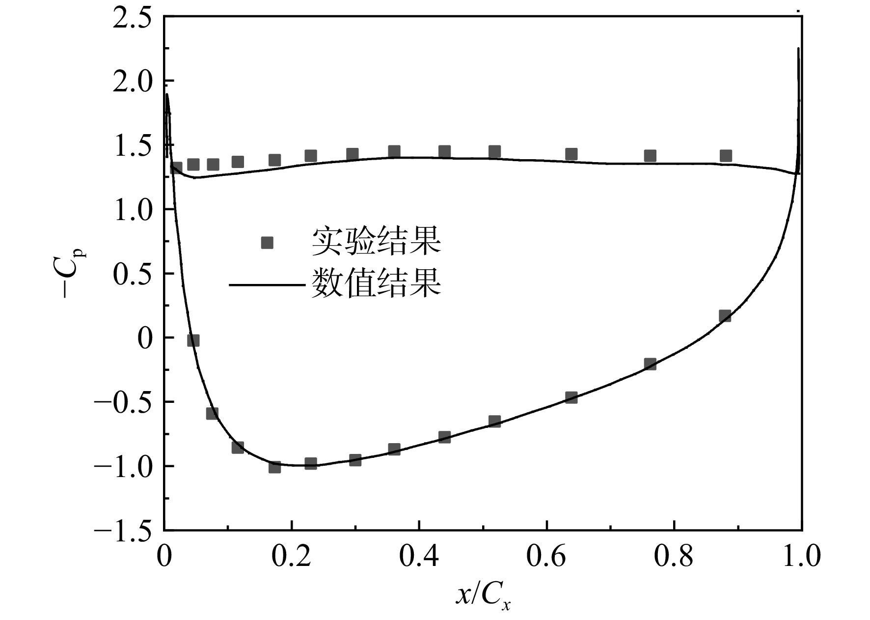
图 3 翼型失速流实验和数值结果对比
Figure 3. Comparison of experimental and numerical results for airfoil stall flow
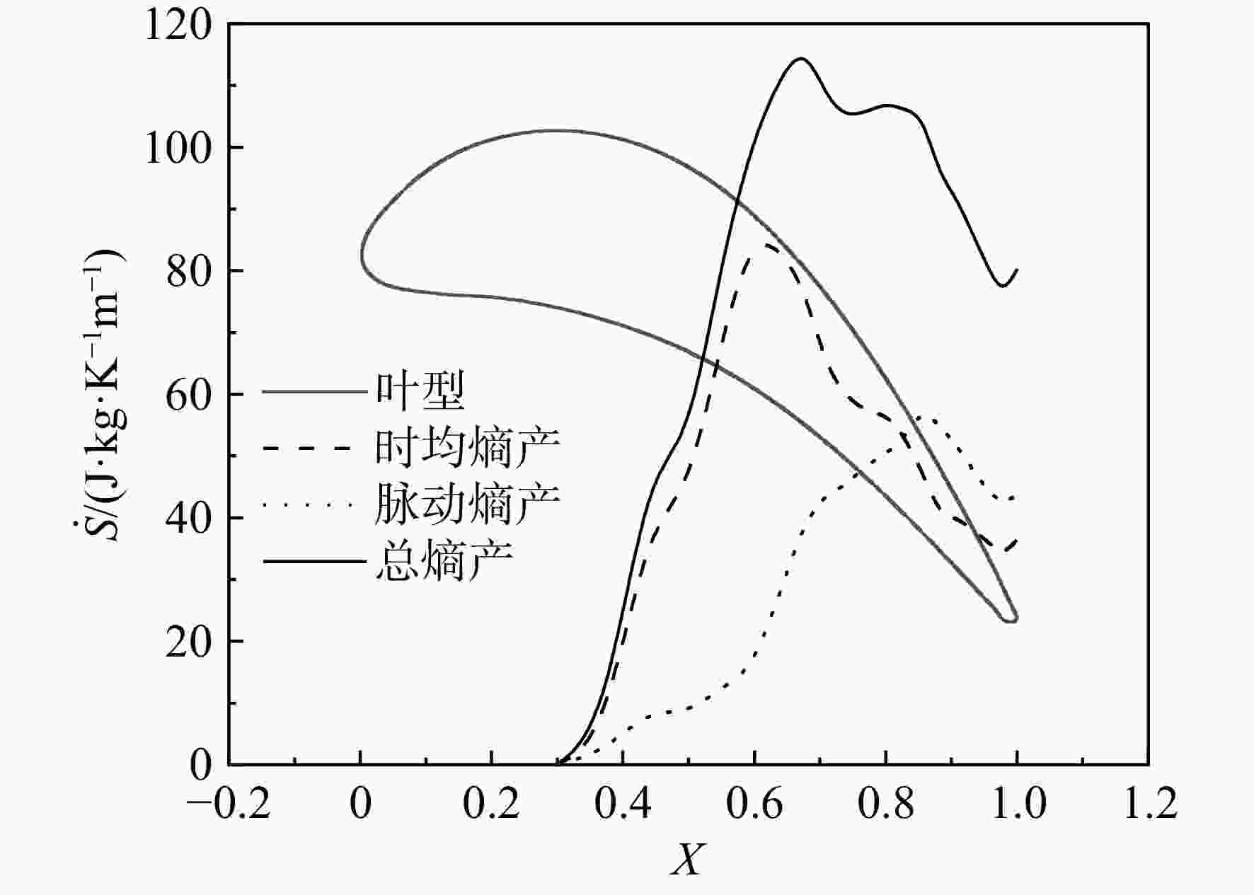
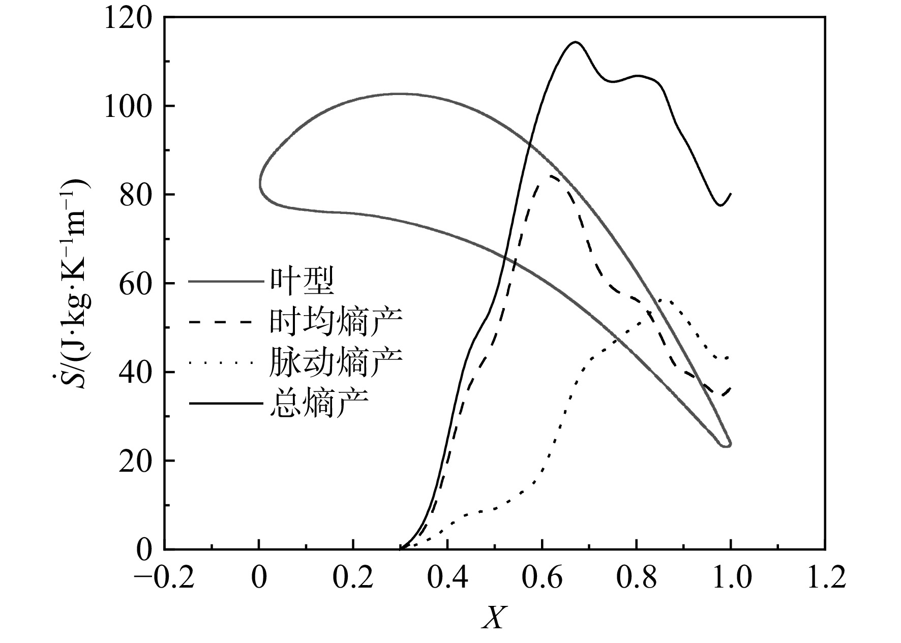
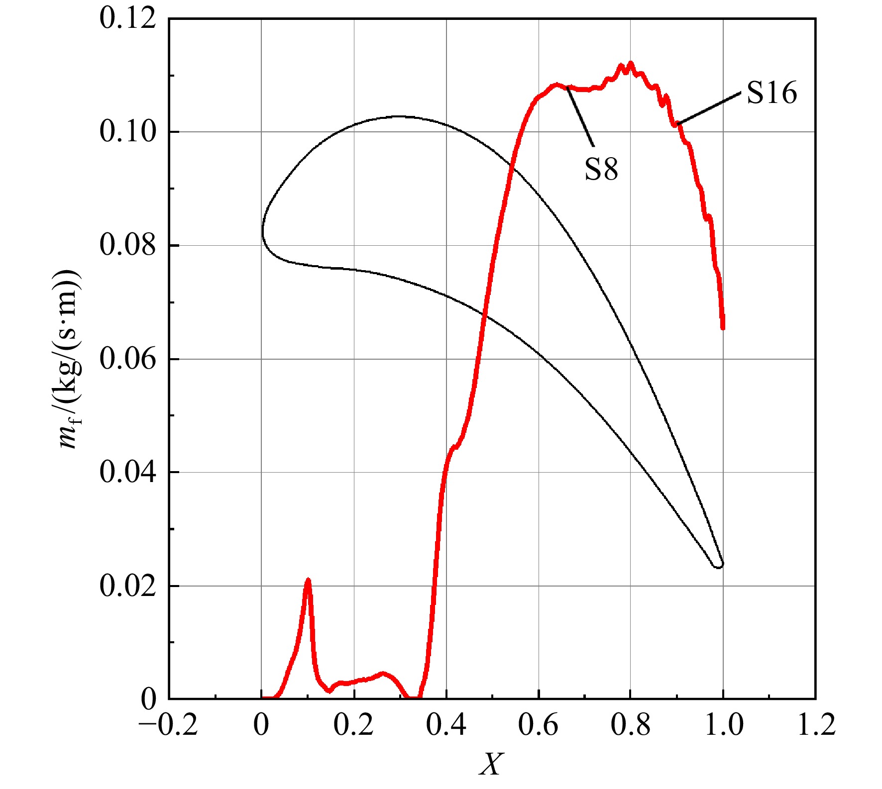
图 4 叶尖区域熵产沿轴向的分布
Figure 4. Axial distribution of entropy production in the rotor tip region
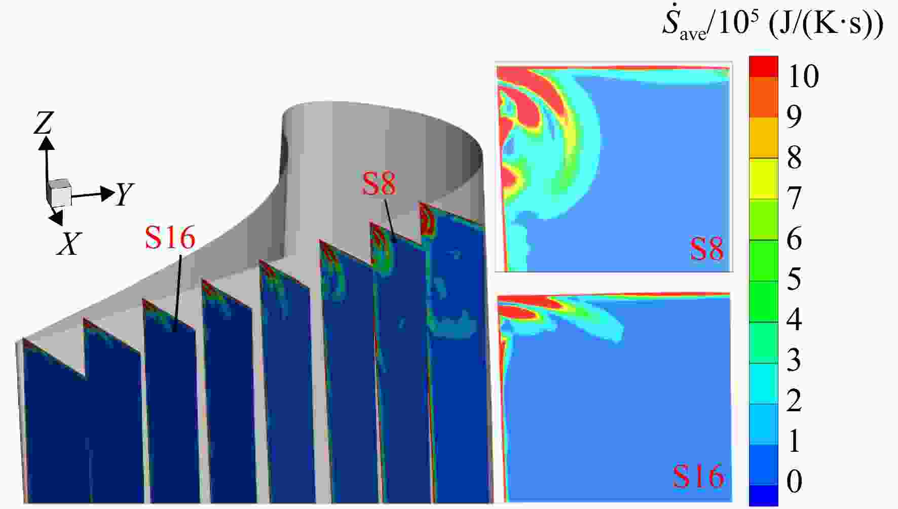
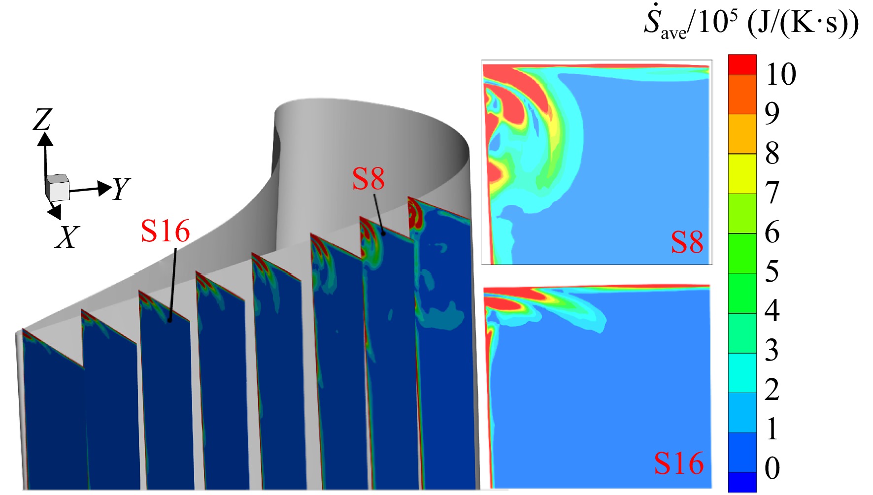
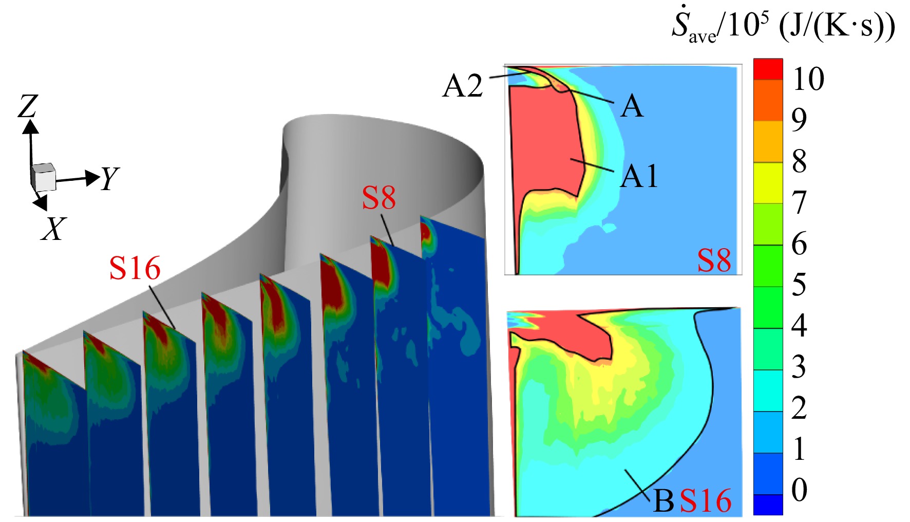
图 5 时均熵产在各流向截面上的空间分布
Figure 5. Time-averaged entropy production’s spatial distribution in various flow cross-sections
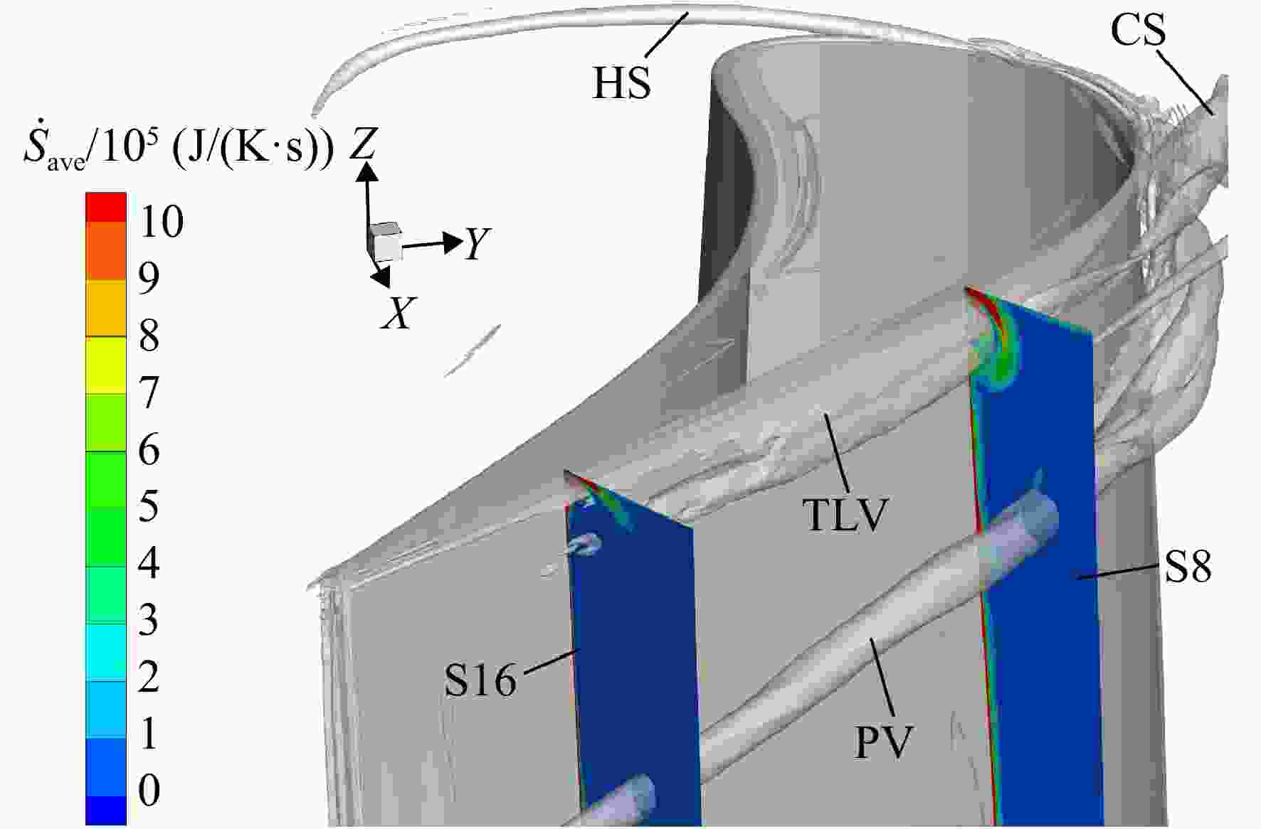
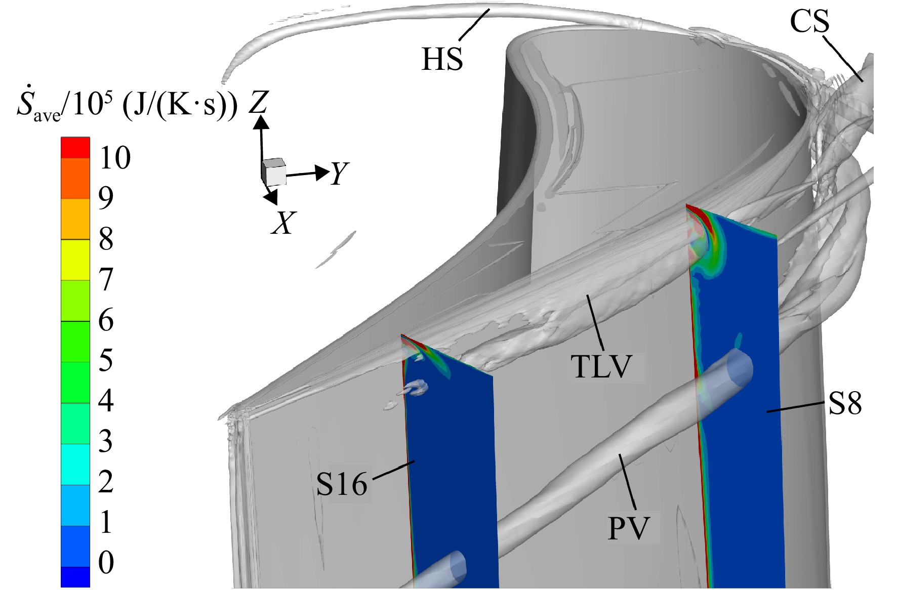
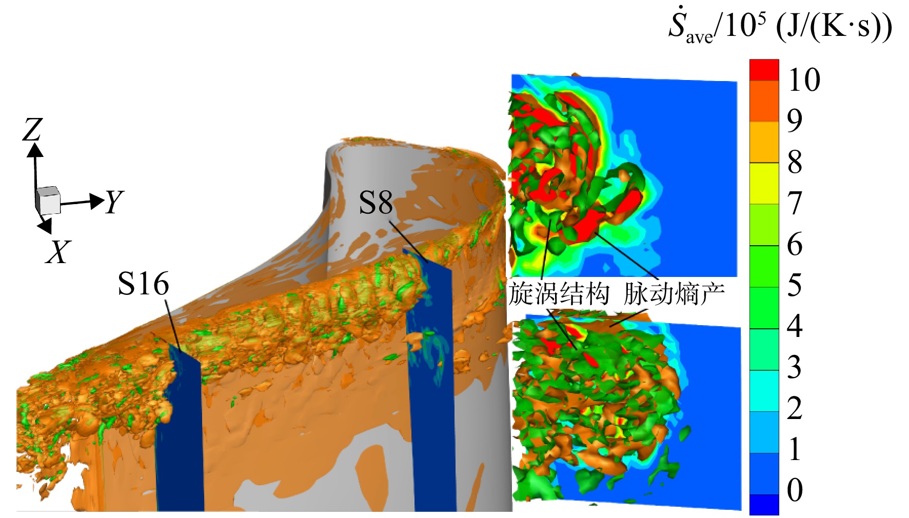
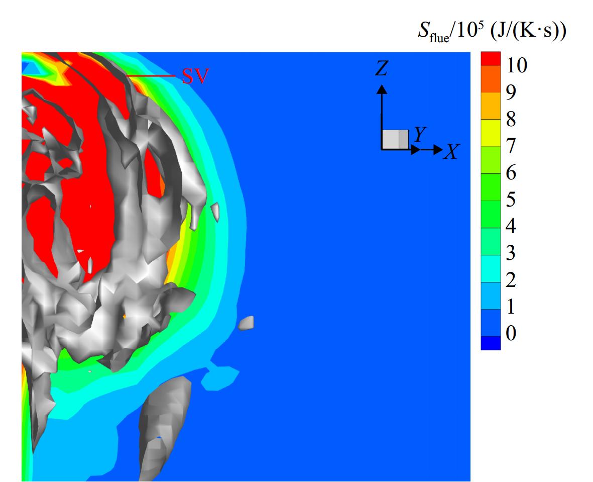
图 7 时均熵产与旋涡结构的空间分布
Figure 7. Spatial distribution of time-averaged entropy production and vortex structures
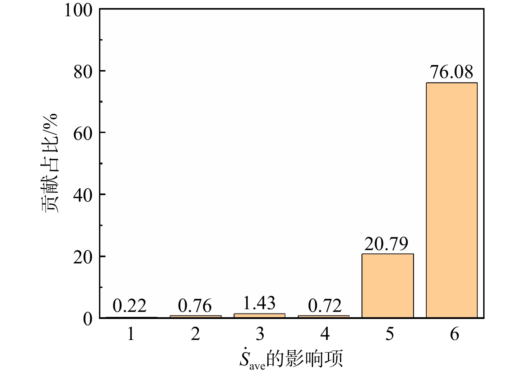
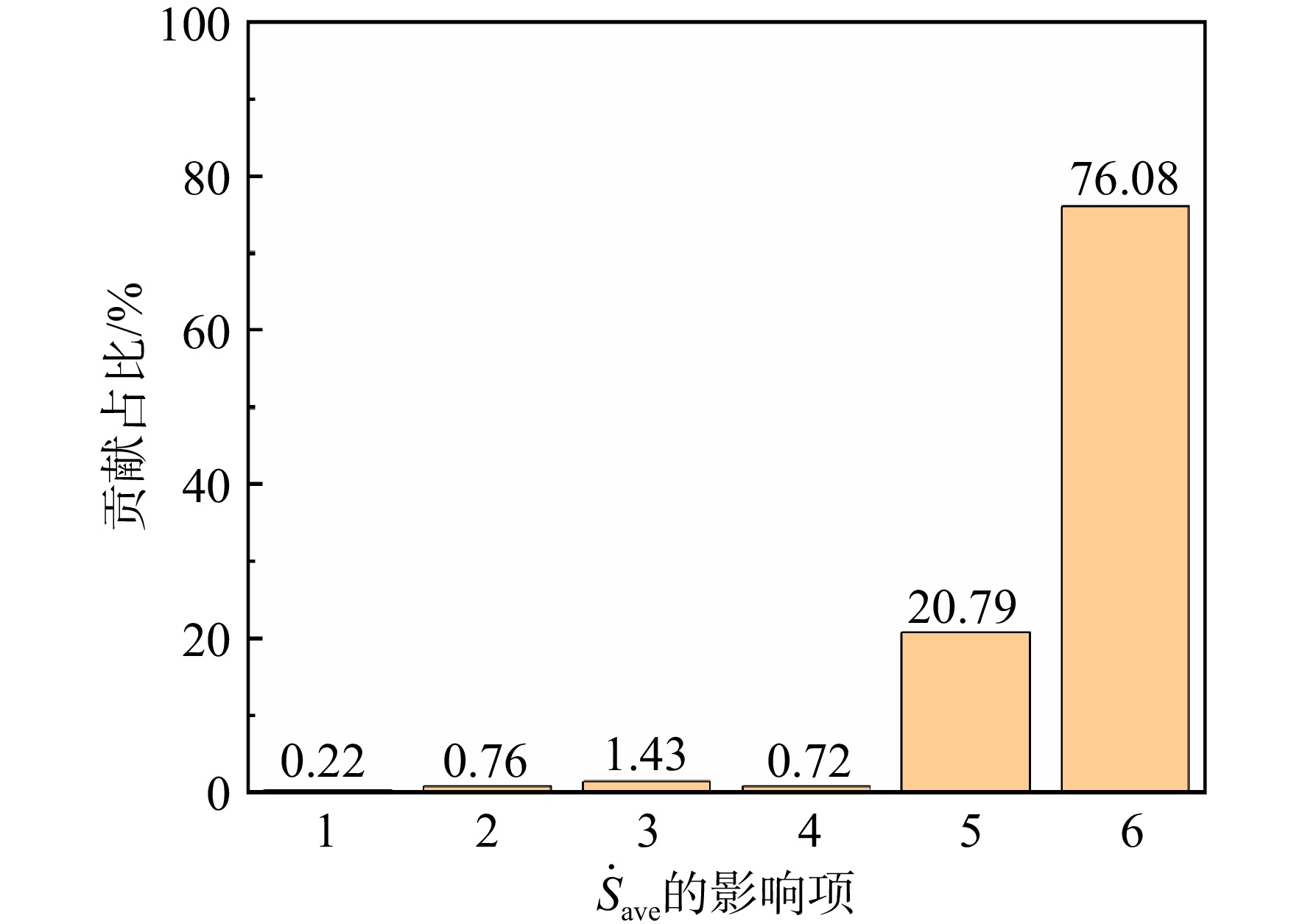
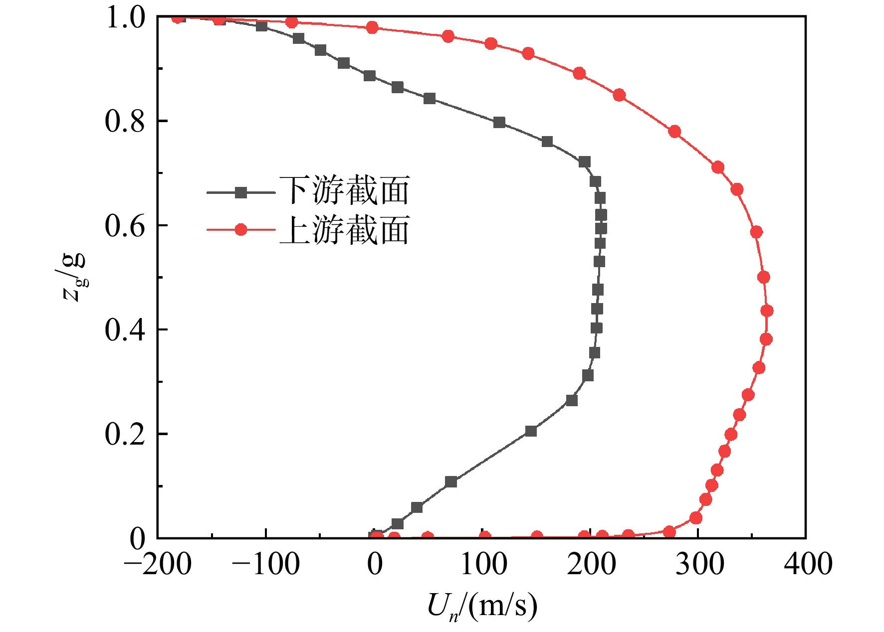
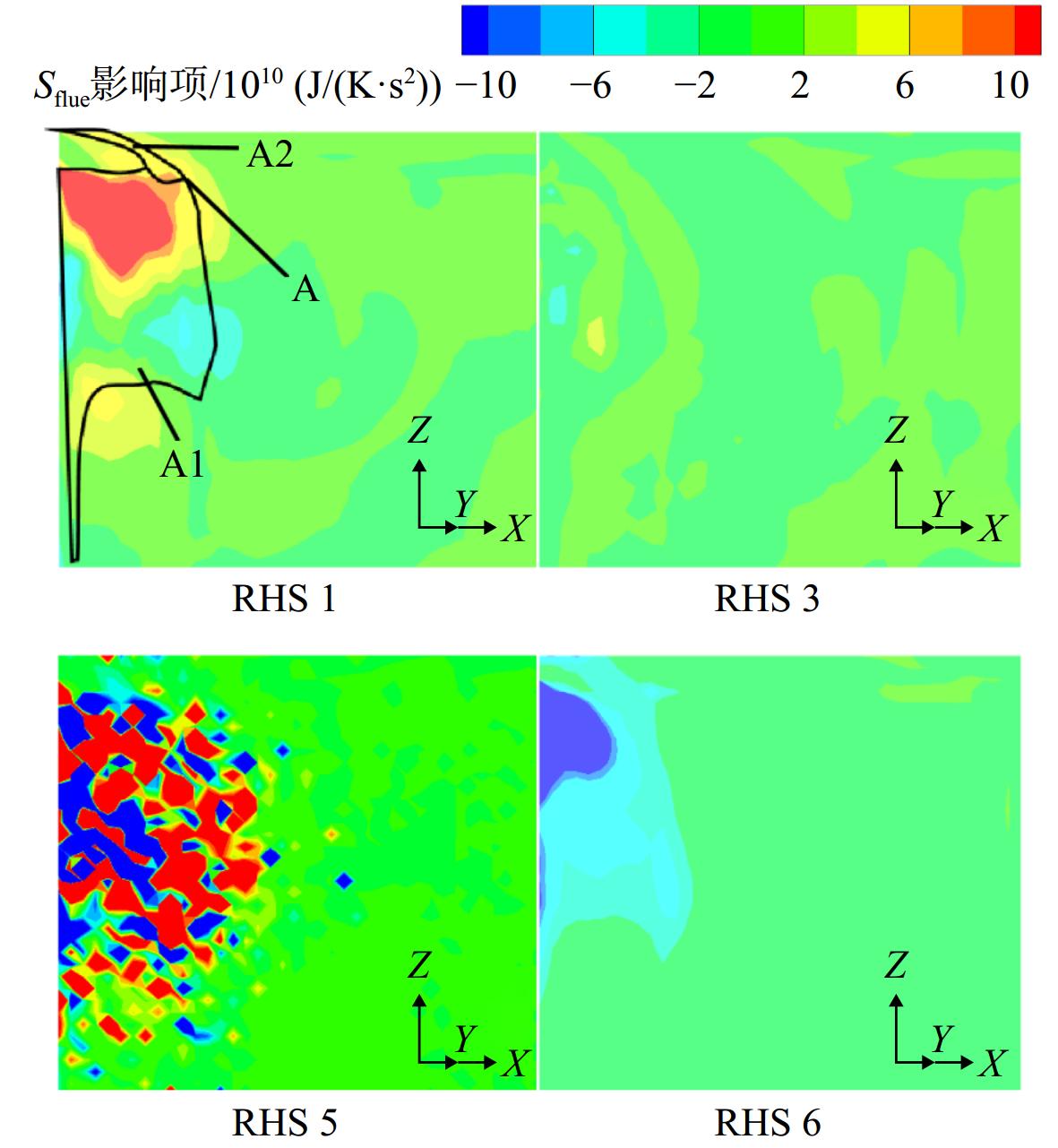
图 8 各项对局部时均熵产的贡献对比
Figure 8. Comparison of contributions of different terms to the local time-averaged entropy production
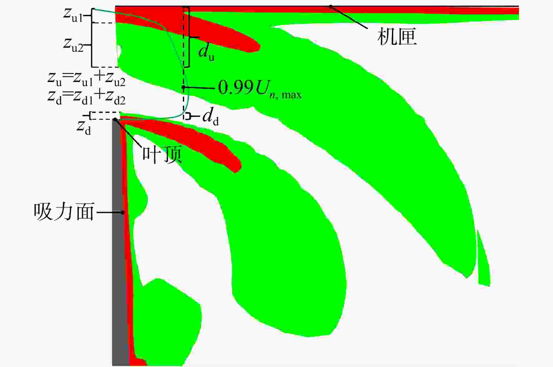
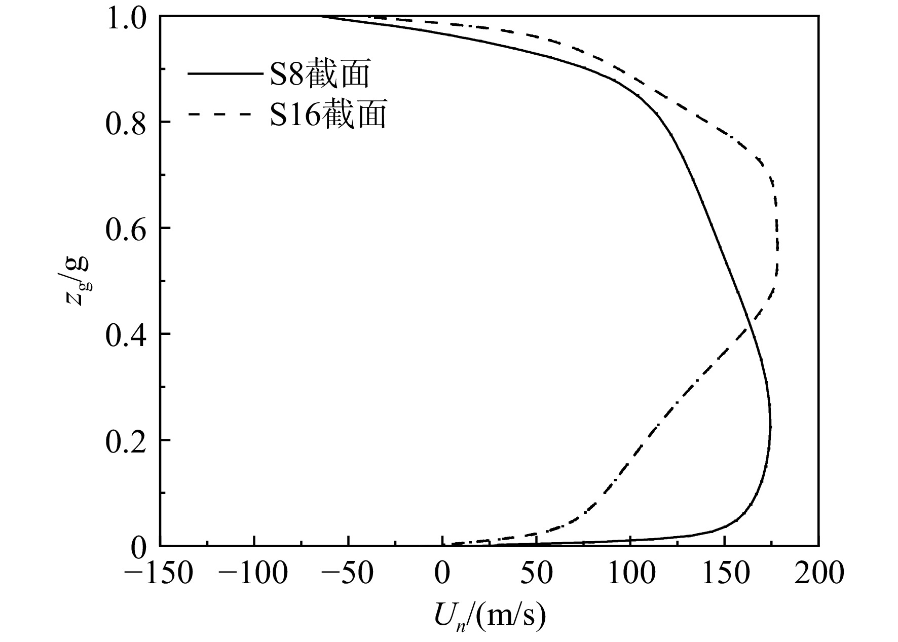
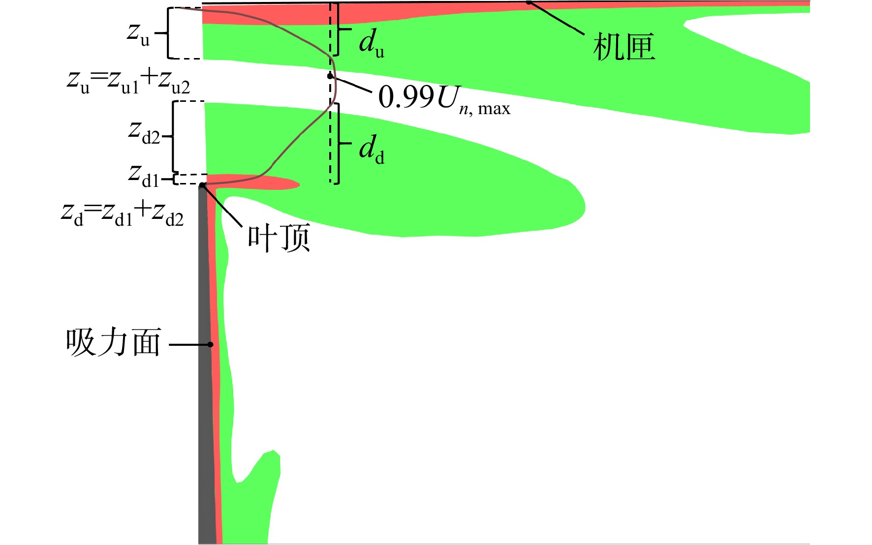
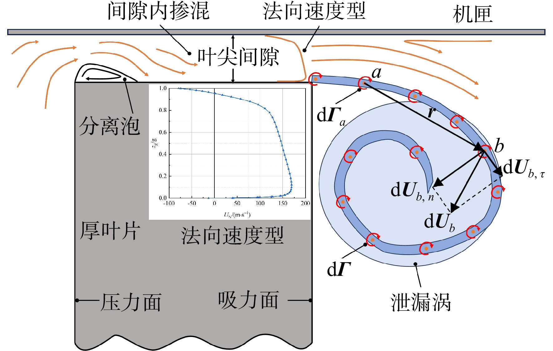
图 10 S8截面叶尖间隙出口法向速度型和高损失区空间分布对比
Figure 10. Comparison of normal velocity profiles at the tip gap exit versus spatial distribution of high-loss regions in S8
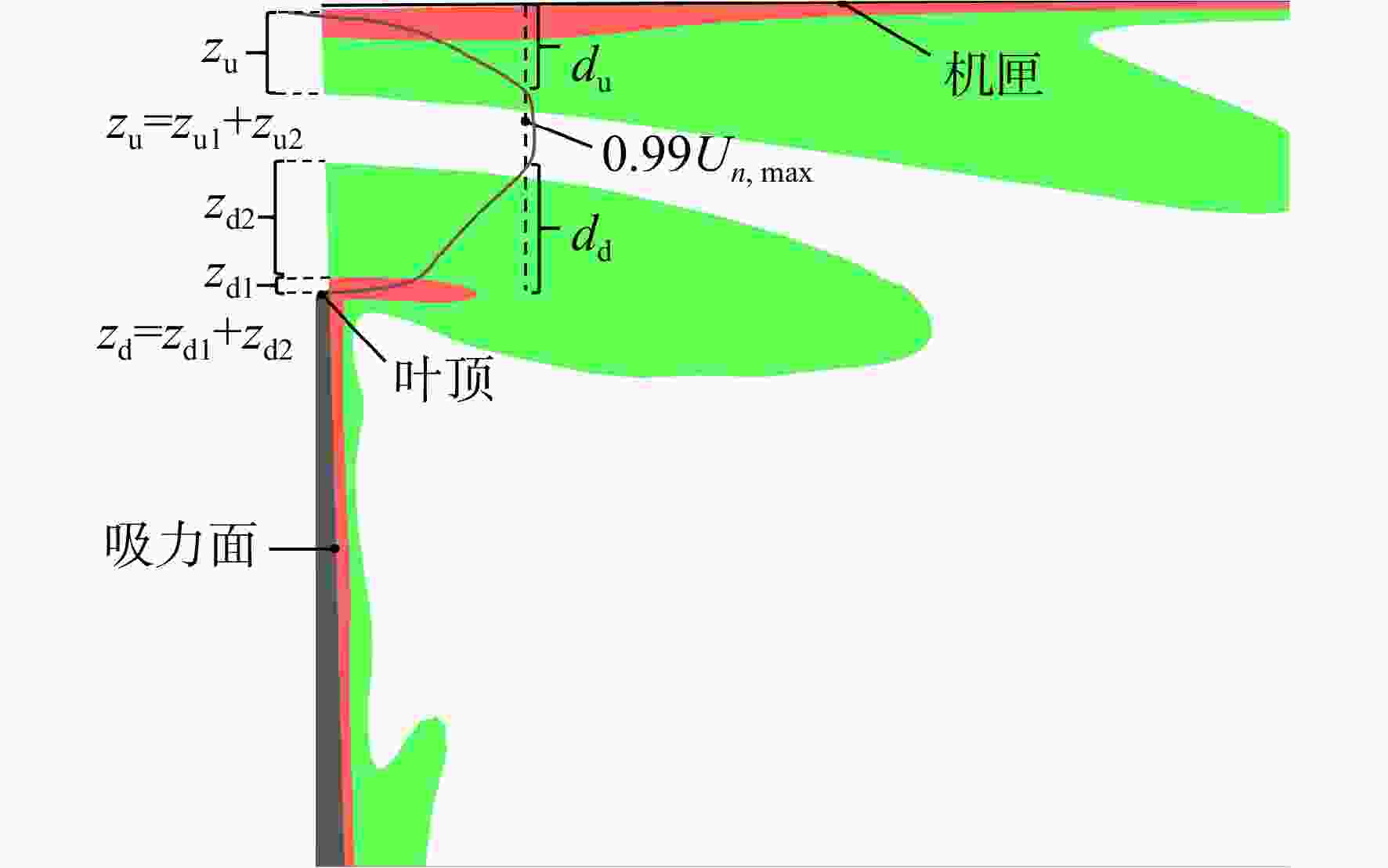
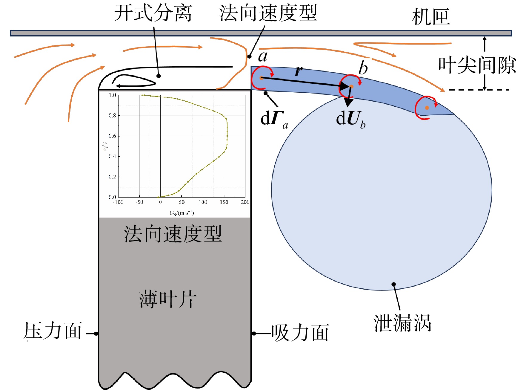
图 11 S16截面叶尖间隙出口法向速度型和高损失区空间分布对比
Figure 11. Comparison of normal velocity profiles at the tip gap exit versus spatial distribution of high-loss regions in S16
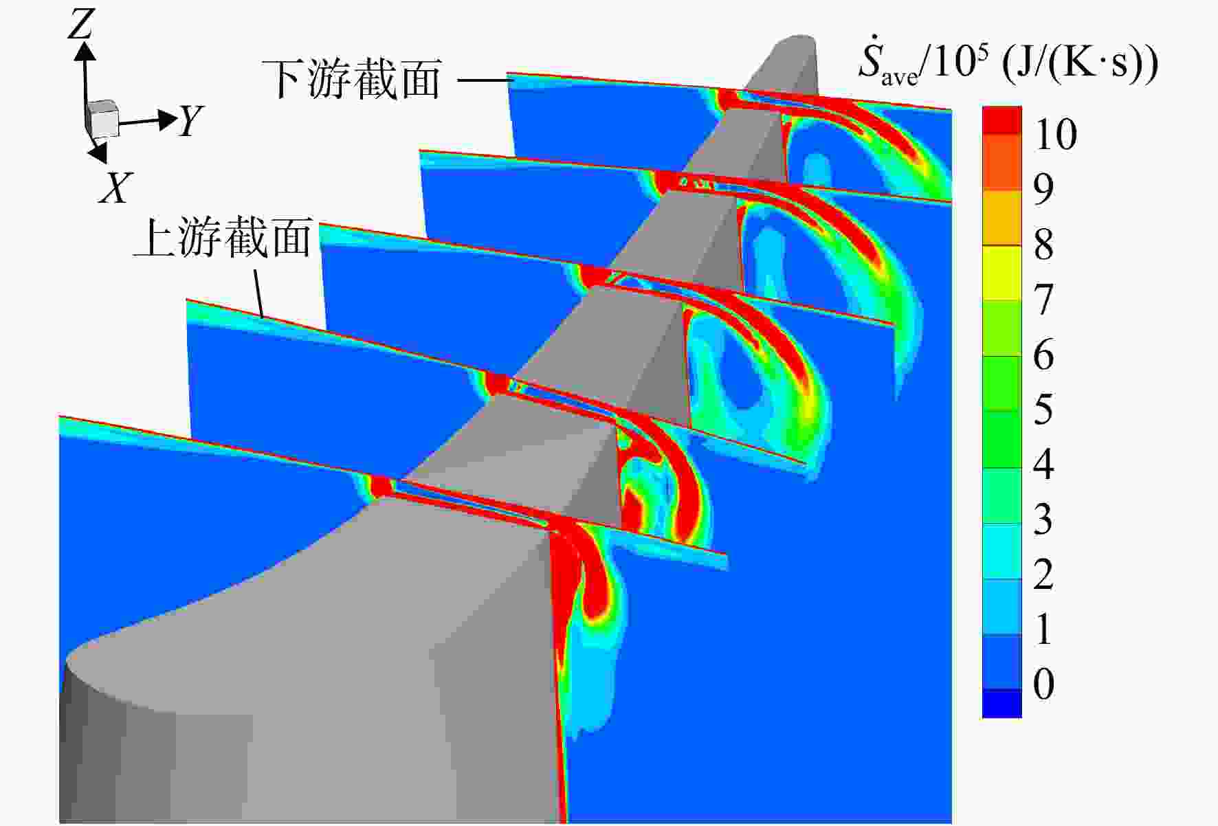
图 14 TTM涡轮转子叶尖区时均熵产的空间分布
Figure 14. Spatial distribution of time-averaged entropy generation in the rotor tip region of a TTM turbine
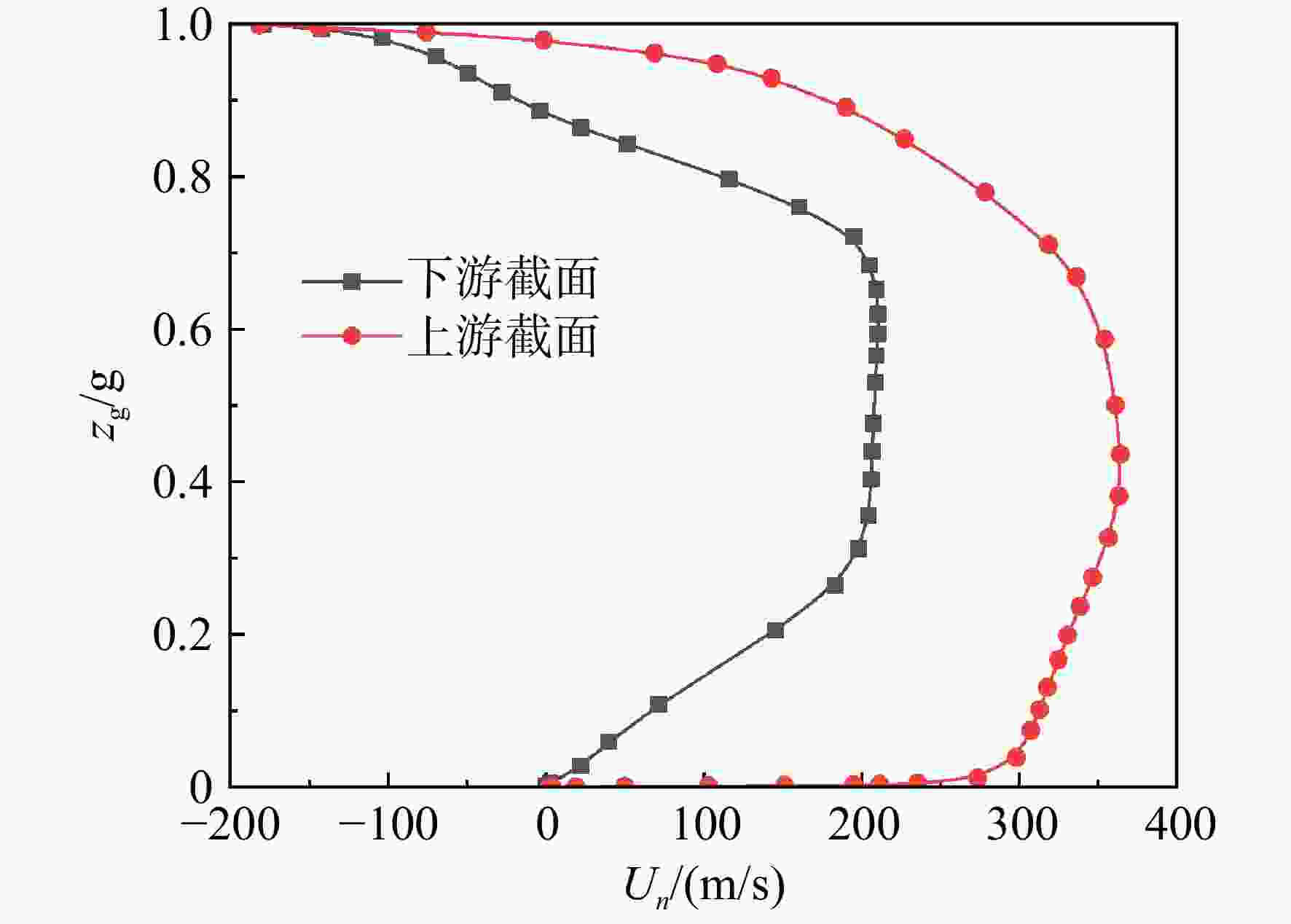
图 15 TTM涡轮间隙出口处法向速度型
Figure 15. Normal velocity profile at the gap exit in TTM turbine
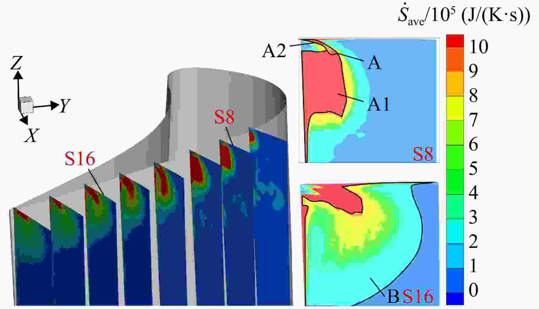
图 16 脉动熵产在各流向截面的空间分布
Figure 16. Fluctuating entropy production’s spatial distribution in various flow cross-sections
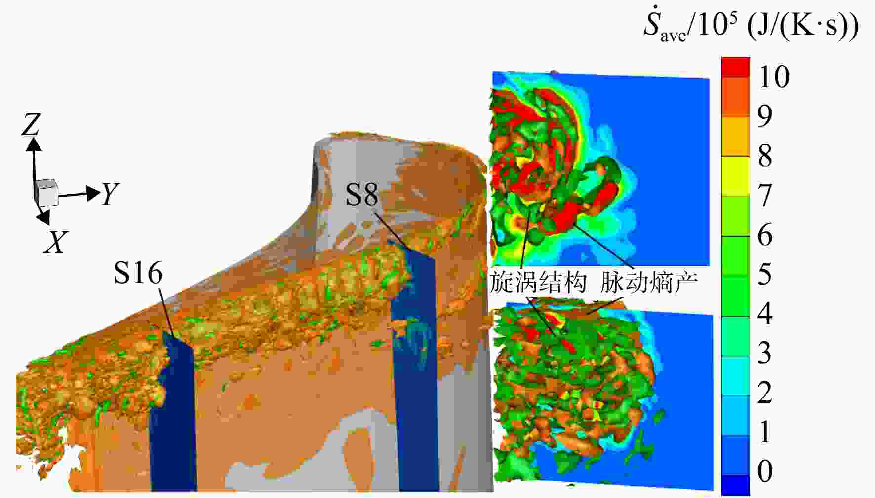
图 17 脉动熵产与旋涡结构的空间分布
Figure 17. Spatial distribution of the fluctuating entropy production and vortex structures
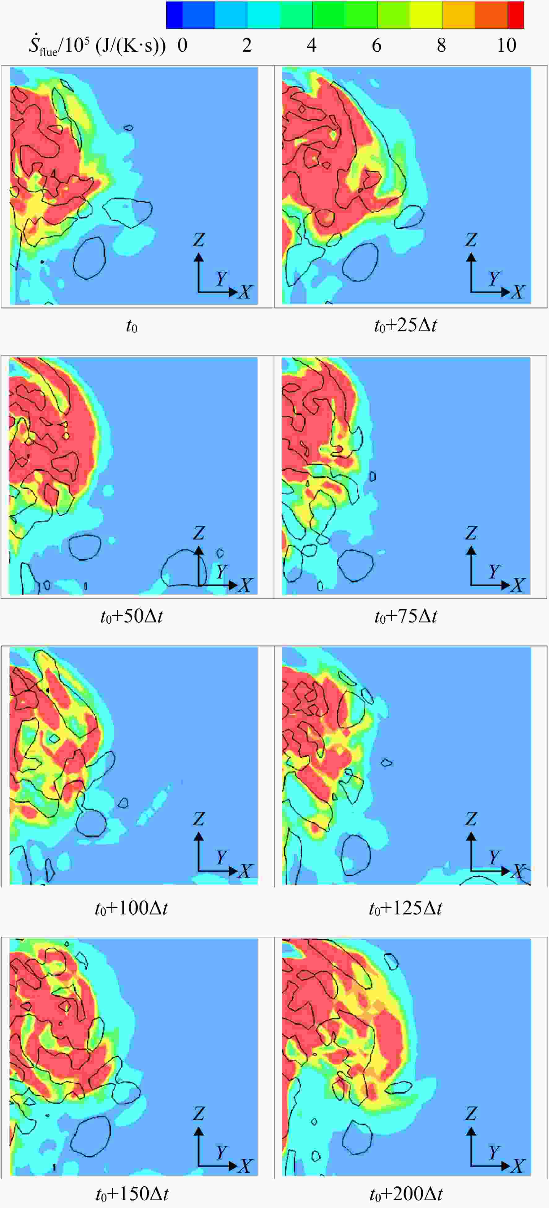
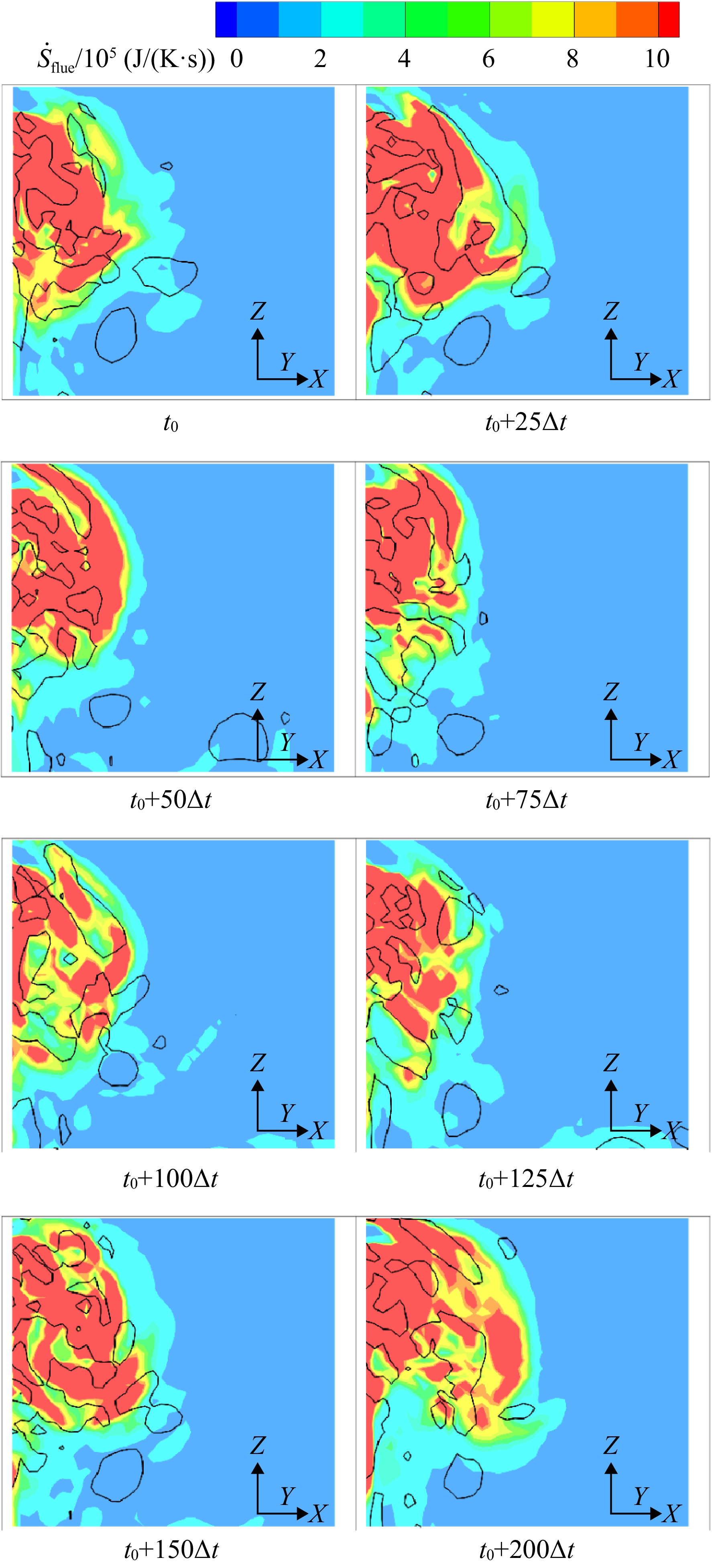
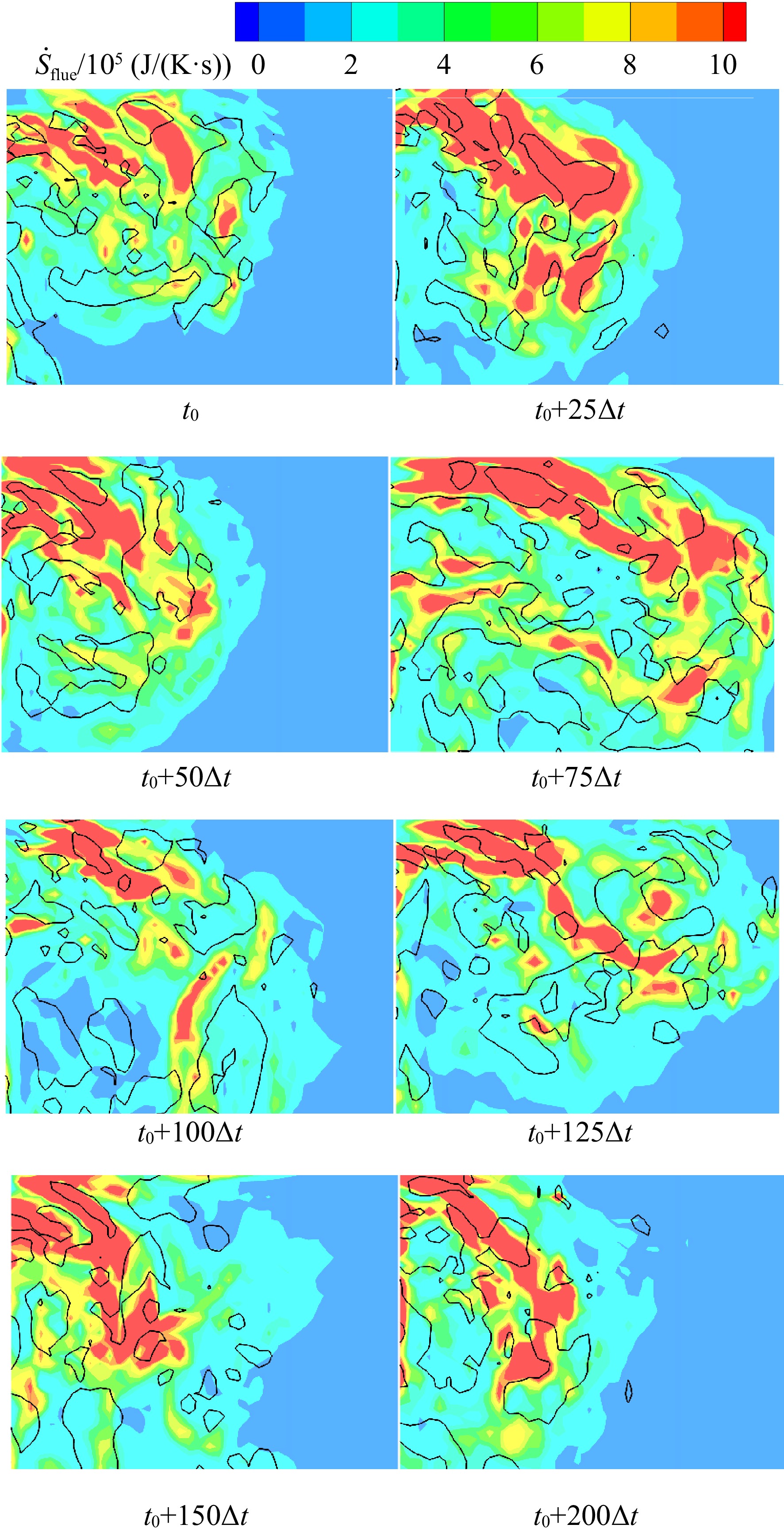
图 18 S8截面不同时刻脉动熵产和旋涡等值线的空间分布
Figure 18. Spatial distribution of the fluctuating entropy production and vortex iso-lines at various times for S8
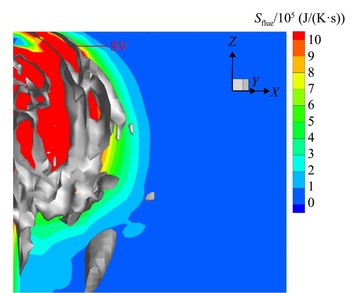
图 19 条件平均脉动熵产分布和旋涡结构
Figure 19. Conditionally averaged fluctuating entropy production distribution and vortical structures
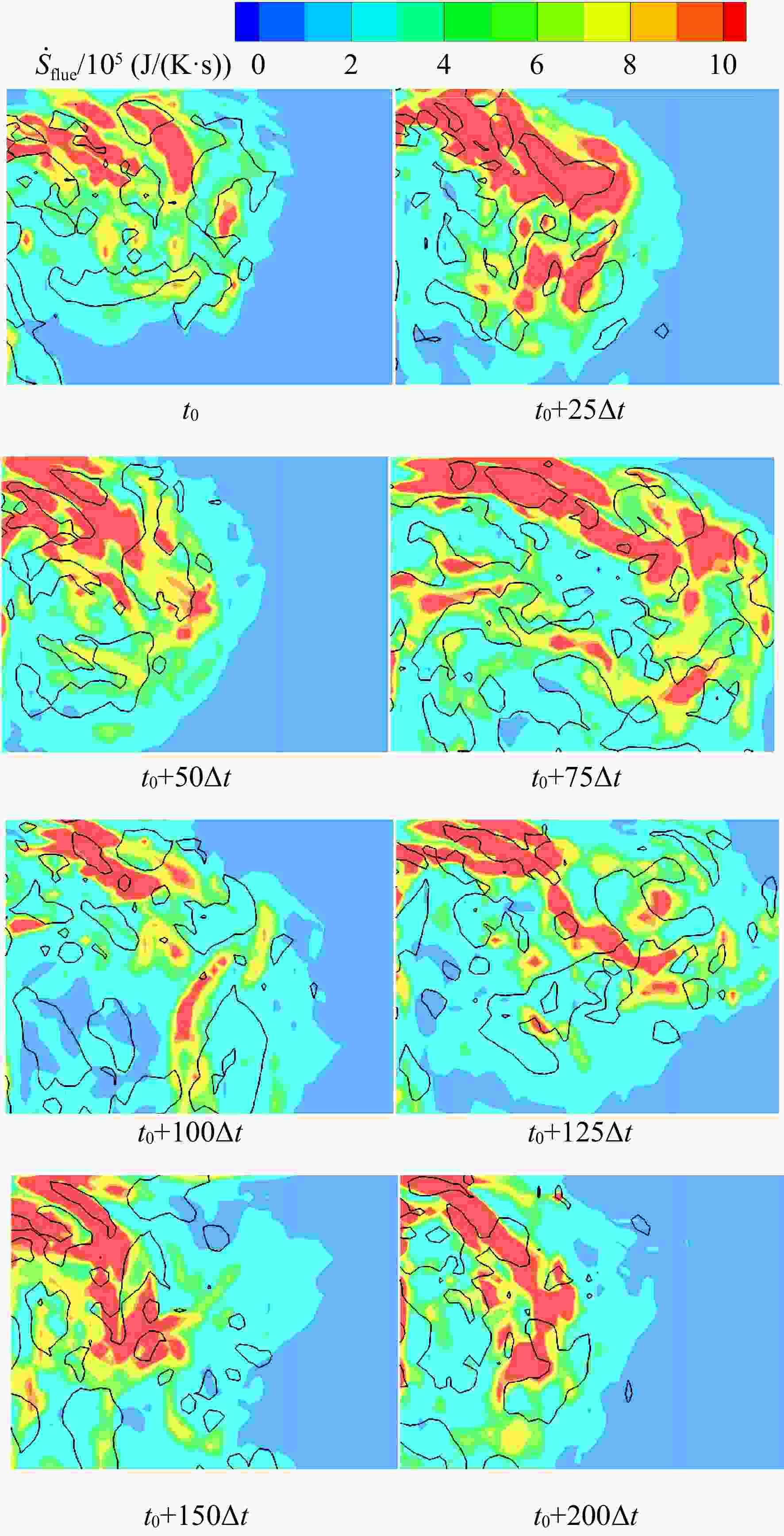
图 21 不同时刻S16脉动熵产和旋涡等值线的空间分布
Figure 21. Spatial distribution of the fluctuating entropy production and vortex iso-lines at various times for S16
表 1 LISA 1.5级涡轮转子主要参数
Table 1. Main parameters of the LISA 1.5 stage rotor
参数 数值 叶片数 54 转速/(r/min) 2700 叶高/mm 70 叶中弦长/mm 59.72 叶中轴向弦长/mm 46.83 叶中节距/mm 42.5 间隙高度/mm 0.68 雷诺数/105 3.8  下载: 导出CSV
表 2 S8和S16处法向速度型的边界层厚度和剪切强度
Table 2. Thickness and shear intensity of the boundary layer in the normal velocity profile at S8 and S16
参数 S8截面 S16截面 dd1/m 4.4208 ×10⁻⁵dd2/m 3.0602 ×10⁻⁴dd/m 9.5018 ×10−53.5023 ×10−4γd/(m/s) 1.9252 ×1065.0337 ×105du1/m 1.0491 ×10−43.4357 ×10−5du2/m 3.8636 ×10−41.9891 ×10−4du/m 4.9127 ×10−42.3326 ×10−4γu/(m/s) 4.8326 ×1057.5577 ×105
下载: 导出CSV
表 3 S8和S16处间隙出口高损失区域厚度
Table 3. Thickness of the high-loss region near the gap exit at S8 and S16
高损失区厚度 S8截面 S16截面 zd1/m 3.0837 ×10−53.3130 ×10−5zd2/m 2.8739 ×10−52.8391 ×10−4zd/m 6.0848 ×10−53.1704 ×10−4zu1/m 9.8306 ×10−56.7803 ×10−5zu2/m 3.1271 ×10−41.4307 ×10−4zu/m 4.1102 ×10−42.1088 ×10−4
下载: 导出CSV
表 4 S8处影响脉动熵产的各项量级对比
Table 4. Comparison of various terms affecting entropy production rate by turbulent dissipation at S8
影响项/(J/(K·s2)) 平均值 最大值 $ \left| {{\text{RHS 1}}} \right| $ 1.2616 ×10103.3899 ×1011$ \left| {{\text{RHS 2}}} \right| $ 3.7664 ×1061.3695 ×108$ \left| {{\text{RHS 3}}} \right| $ 2.0246 ×1093.1645 ×1010$ \left| {{\text{RHS 4}}} \right| $ 3.0080 ×1051.3033 ×107$ \left| {{\text{RHS 5}}} \right| $ 2.8012 ×10101.1175 ×1012$ \left| {{\text{RHS 6}}} \right| $ 1.5862 ×10101.9295 ×1012
下载: 导出CSV
表 5 S16处影响脉动熵产变化的各项量级对比
Table 5. Comparison of various terms affecting entropy production rate by turbulent dissipation at S16
影响项/(J/(K·s2)) 平均值 最大值 $ \left| {{\text{RHS 1}}} \right| $ 1.0965 ×10106.4874 ×1010$ \left| {{\text{RHS 2}}} \right| $ 3.1695 ×1062.1715 ×107$ \left| {{\text{RHS 3}}} \right| $ 1.3889 ×1091.2183 ×1010$ \left| {{\text{RHS 4}}} \right| $ 2.5964 ×1051.2153 ×106$ \left| {{\text{RHS 5}}} \right| $ 4.9573 ×10106.9978 ×1012$ \left| {{\text{RHS 6}}} \right| $ 9.9205 ×1092.0764 ×1011
下载: 导出CSV
-
[1] DENTON J D. The 1993 IGTI scholar lecture: loss mechanisms in turbomachines[J]. Journal of Turbomachinery, 1993, 115(4): 621-656. doi: 10.1115/1.2929299 [2] BINDON J P. The measurement and formation of tip clearance loss[J]. Journal of Turbomachinery, 1989, 111(3): 257-263. doi: 10.1115/1.3262264 [3] DISHART P T, MOORE J. Tip leakage losses in a linear turbine cascade[J]. Journal of Turbomachinery, 1990, 112(4): 599-608. doi: 10.1115/1.2927700 [4] YARAS M I, SJOLANDER S A. Prediction of tip-leakage losses in axial turbines[J]. Journal of Turbomachinery, 1992, 114(1): 204-210. doi: 10.1115/1.2927987 [5] ZOU Zhengping, SHAO Fei, LI Yiran, et al. Dominant flow structure in the squealer tip gap and its impact on turbine aerodynamic performance[J]. Energy, 2017, 138: 167-184. doi: 10.1016/j.energy.2017.07.047 [6] RAINS D A. Tip clearance flows in axial flow compressors and pumps[D]. Pasadena, US: California Institute of Technology, 1954. [7] YOUNG J B, WILCOCK R C. Modeling the air-cooled gas turbine: Part 2 coolant flows and losses[J]. Journal of Turbomachinery, 2002, 124(2): 214-221. doi: 10.1115/1.1415038 [8] YANG Hongkai, ZHANG Weihao, ZOU Zhengping, et al. The development and applications of a loading distribution based tip leakage loss model for unshrouded gas turbines[J]. Journal of Turbomachinery, 2020, 142(7): 071005. doi: 10.1115/1.4047382 [9] MISCHO B, BEHR T, ABHARI R S. Flow physics and profiling of recessed blade tips: impact on performance and heat load[J]. Journal of Turbomachinery, 2008, 130(2): 021008. doi: 10.1115/1.2775485 [10] KEGALJ M, SCHMID G, WARTZEK F, et al. Experimental and numerical investigation of tip leakage flow in a 1 1/2 stage turbine rig comparing flat and cavity-squealer tip geometries[C]//Turbo Expo: Power for Land, Sea, and Air. American Society of Mechanical Engineers. Copenhagen, Denmark: American Society of Mechanical Engineers, 2012: 1543-1557. [11] LAMPART P. Tip leakage flows in turbines[J]. Task Quarterly, 2006, 10(2): 139-175. [12] GAO Jie, ZHENG Qun, XU Tianbang, et al. Inlet conditions effect on tip leakage vortex breakdown in unshrouded axial turbines[J]. Energy, 2015, 91: 255-263. doi: 10.1016/j.energy.2015.08.065 [13] HUANG A A C. Loss mechanisms in turbine tip clearance flows[D]. Boston, US: Massachusetts Institute of Technology, 2011. [14] LI Hui, SU Xinrong, YUAN Xin. Entropy analysis of the flat tip leakage flow with delayed detached eddy simulation[J]. Entropy, 2018, 21(1): 21. doi: 10.3390/e21010021 [15] BEHR T. Control of rotor tip leakage and secondary flow by casing air injection in unshrounded axial turbines[D]. Dresden, Germany: Dresden University of Technology, 2007. [16] 邵飞. 涡轮叶尖泄漏精细流动机理及组织方法[D]. 北京: 北京航空航天大学, 2017. SHAO Fei. Flow mechanism and organizing method for the turbine tip leakage flow [D]. Beijing: Beihang University, 2017. (in ChineseSHAO Fei. Flow mechanism and organizing method for the turbine tip leakage flow [D]. Beijing: Beihang University, 2017. (in Chinese) [17] NING Fangfei. A CFD package for turbomachinery flow simulation and aerodynamic design optimization[R]. ASME Paper GT2014-26515, 2014. [18] 杜磊. 压气机内部复杂流动的尺度自适应模拟[D]. 北京: 北京航空航天大学, 2014. DU Lei. Scale Adaptive Simulation of complex flows in axial compressors [D]. Beijing: Beihang University, 2014. (in ChineseDU Lei. Scale Adaptive Simulation of complex flows in axial compressors [D]. Beijing: Beihang University, 2014. (in Chinese) [19] KOCK F, HERWIG H. Entropy production calculation for turbulent shear flows and their implementation in cfd codes[J]. International Journal of Heat and Fluid Flow, 2005, 26(4): 672-680. doi: 10.1016/j.ijheatfluidflow.2005.03.005 [20] CANTWELL B J. Exact solution of a restricted Euler equation for the velocity gradient tensor[J]. Physics of Fluids A: Fluid Dynamics, 1992, 4(4): 782-793. doi: 10.1063/1.858295 [21] JEONG J, HUSSAIN F. On the identification of a vortex[J]. Journal of Fluid Mechanics, 1995, 285: 69-94. doi: 10.1017/S0022112095000462 [22] 王洪伟. 我所理解的流体力学[M]. 2版. 北京: 国防工业出版社, 2019. WANG Hongwei. Fluid mechanics as I understand it[M]. 2nd ed. Beijing: National Defense Industry Press, 2019. (in ChineseWANG Hongwei. Fluid mechanics as I understand it[M]. 2nd ed. Beijing: National Defense Industry Press, 2019. (in Chinese) [23] WATANABE T, NAGATA K. The response of small-scale shear layers to perturbations in turbulence[J]. Journal of Fluid Mechanics, 2023, 963: A31. doi: 10.1017/jfm.2023.316 [24] 吴望一. 流体力学(上)[M]. 北京: 北京大学出版社, 2004. WU Wangyi. Fluid mechanics (volume 1) [M]. Beijing: Peking University Press, 2004. (in ChineseWU Wangyi. Fluid mechanics (volume 1) [M]. Beijing: Peking University Press, 2004. (in Chinese) [25] ERHARD J. Design, construction and commissioning of a transonic test turbine facility[D]. Graz, Austria: University of Technology, 2000. [26] CHEVILLARD L, MENEVEAU C, BIFERALE L, et al. Modeling the pressure hessian and viscous Laplacian in turbulence: comparisons with direct numerical simulation and implications on velocity gradient dynamics[J]. Physics of Fluids, 2008, 20(10): 101504. -



 点击查看大图

计量
- 文章访问数: 424
- HTML浏览量: 276
- PDF量: 41
- 被引次数: 0