






Optimization theory of vibration energy transmission for mid turbine frame dual rotor system
-
摘要:
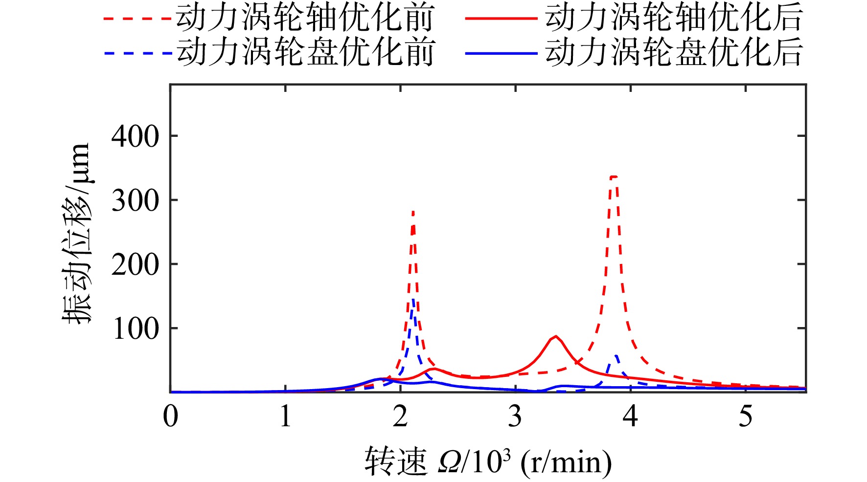
为优化共用支承结构双转子系统的不平衡响应特性,使其在同等不平衡量下能够在较大的转速范围内稳定运行,建立了共用支承结构双转子系统的简化质点模型振动微分方程。基于动力吸振器经典理论对该简化模型进行了理论推导和计算,证明振系内质量块之间存在振动能量的转移,并得到了通过振动能量转移实现最大减振效率的刚度组合条件和阻尼条件。基于上述方法对某型共用支承结构双转子系统的模拟实验器进行了刚度优化。使用有限元法对优化前后的模型进行动力学特性和不平衡响应计算,证明了振动能量转移现象仍然存在,优化后的动力涡轮轴在关键模态下应变能占比下降超过31.9%,优化后动力涡轮轴响应下降超过73.0%,动力涡轮盘响应下降超过55.3%,说明使用振动能量转移的优化理论对共用支承结构双转子系统进行优化能够有效降低系统的不平衡响应。
Abstract:In order to optimize the unbalance response feature of a mid turbine frame dual rotor system, and can make it operate stably within a large speed range under the same unbalance mass, a simplified particles system was established based on the mid turbine frame dual rotor system. It was proved that there was vibration energy transmission between the particles in the simplified particles system based on the dynamic vibration absorber theory deduction. The stiffness combination and damping conditions with the best vibration energy transmission efficiency were calculated. According to the ideas above, the support stiffness of a dual-rotor system test rig with mid turbine frame was optimized. The finite element method was used to analyze the rotor dynamics feature and its unbalance response. The result showed that the rotor system also had a similar vibration energy transmission phenomenon. After the optimization, the strain energy proportion of the power turbine shaft in the key mode decreased by more than 31.9%. Compared with the unoptimized rotor system, the unbalance response of power turbine shaft decreased by more than 73.0% and the response of the power turbine disk dedcreased by more than 55.3%, indicating that using the vibration energy transmission method to optimize a mid turbine frame dual rotor system can reduce the unbalanced response of the system effectively.
-

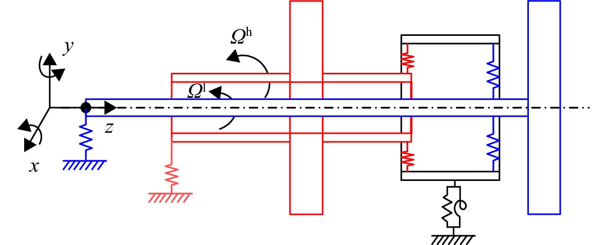
图 1 典型共用支承结构发动机双转子结构简图
Figure 1. Typical structure of the dual rotor system with mid turbine frame

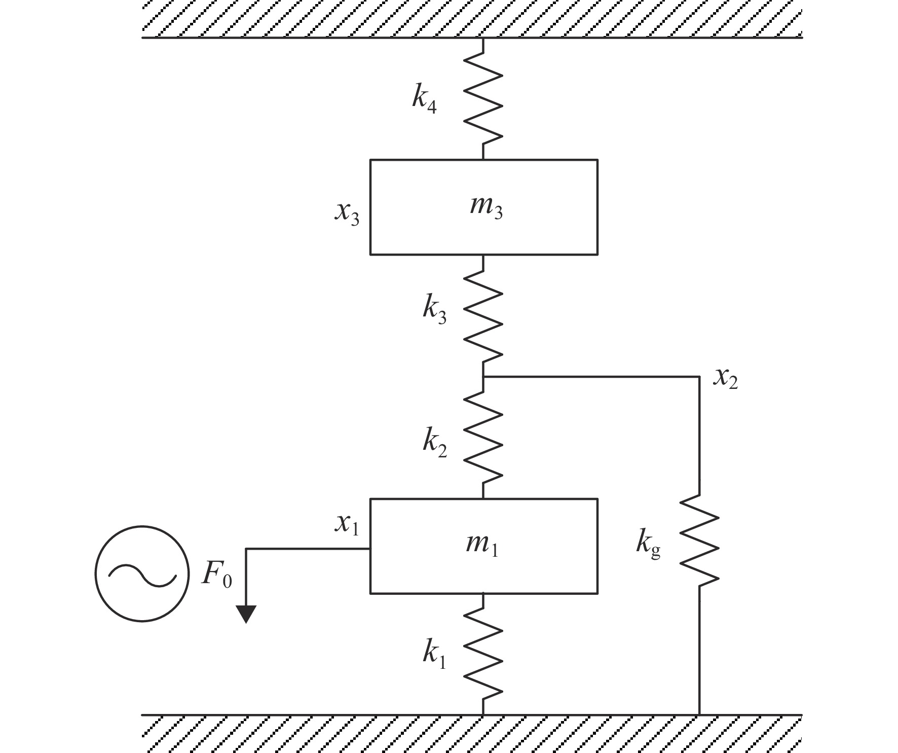
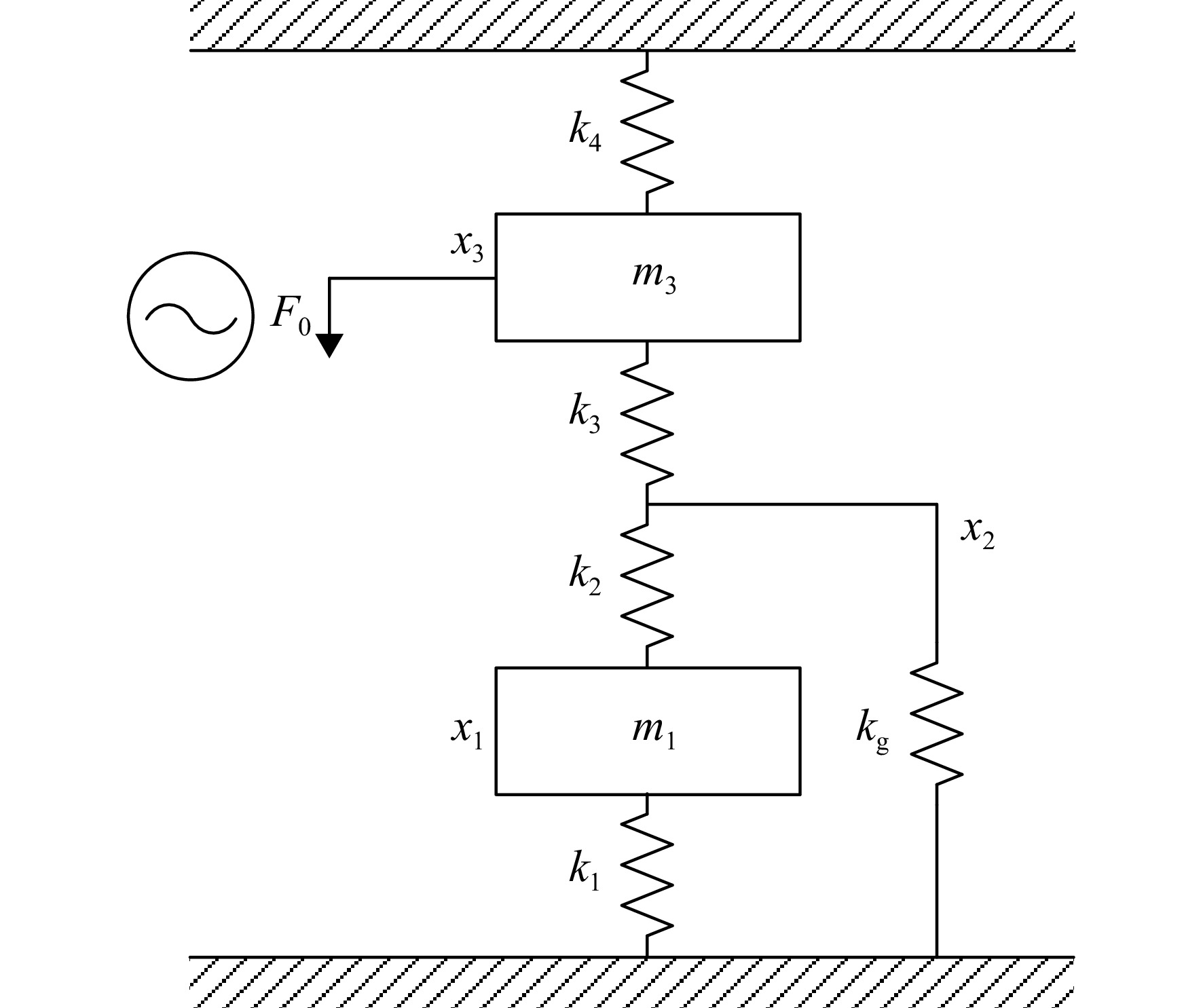
图 3 不考虑m2和所有阻尼的简化振系(振系0)
Figure 3. Simplified system model set m2 and all damper aside (system 0)

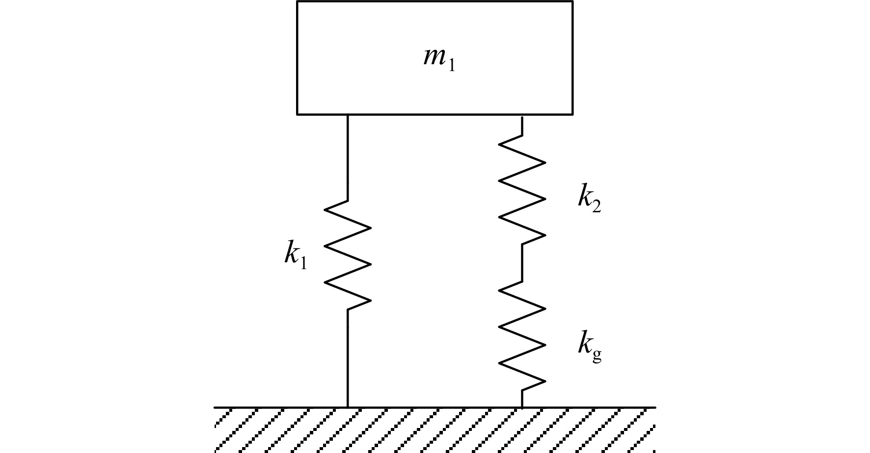
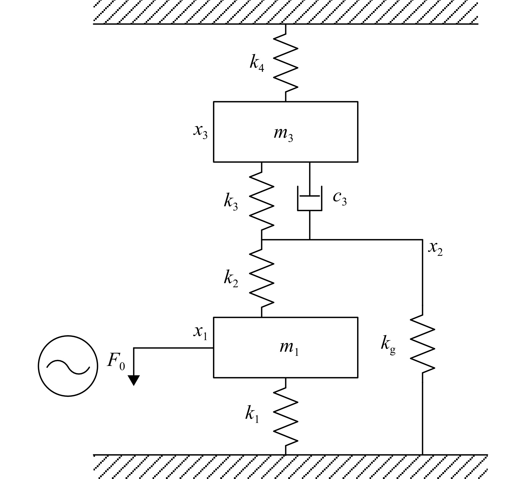
图 4 仅考虑质量块$m_1 $的振系(振系1)
Figure 4. Particle system model only considers $m_1 $ (system 1)

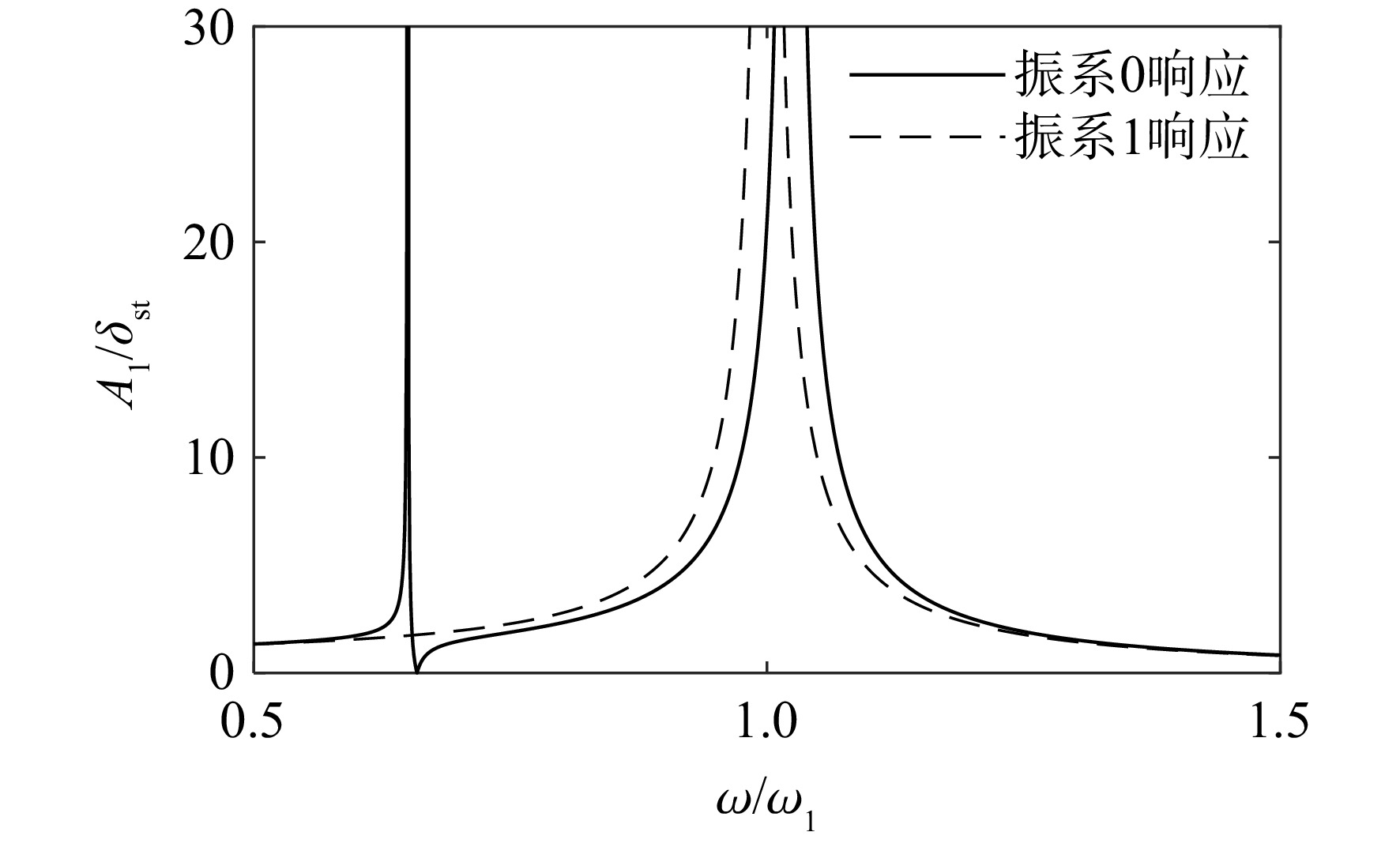
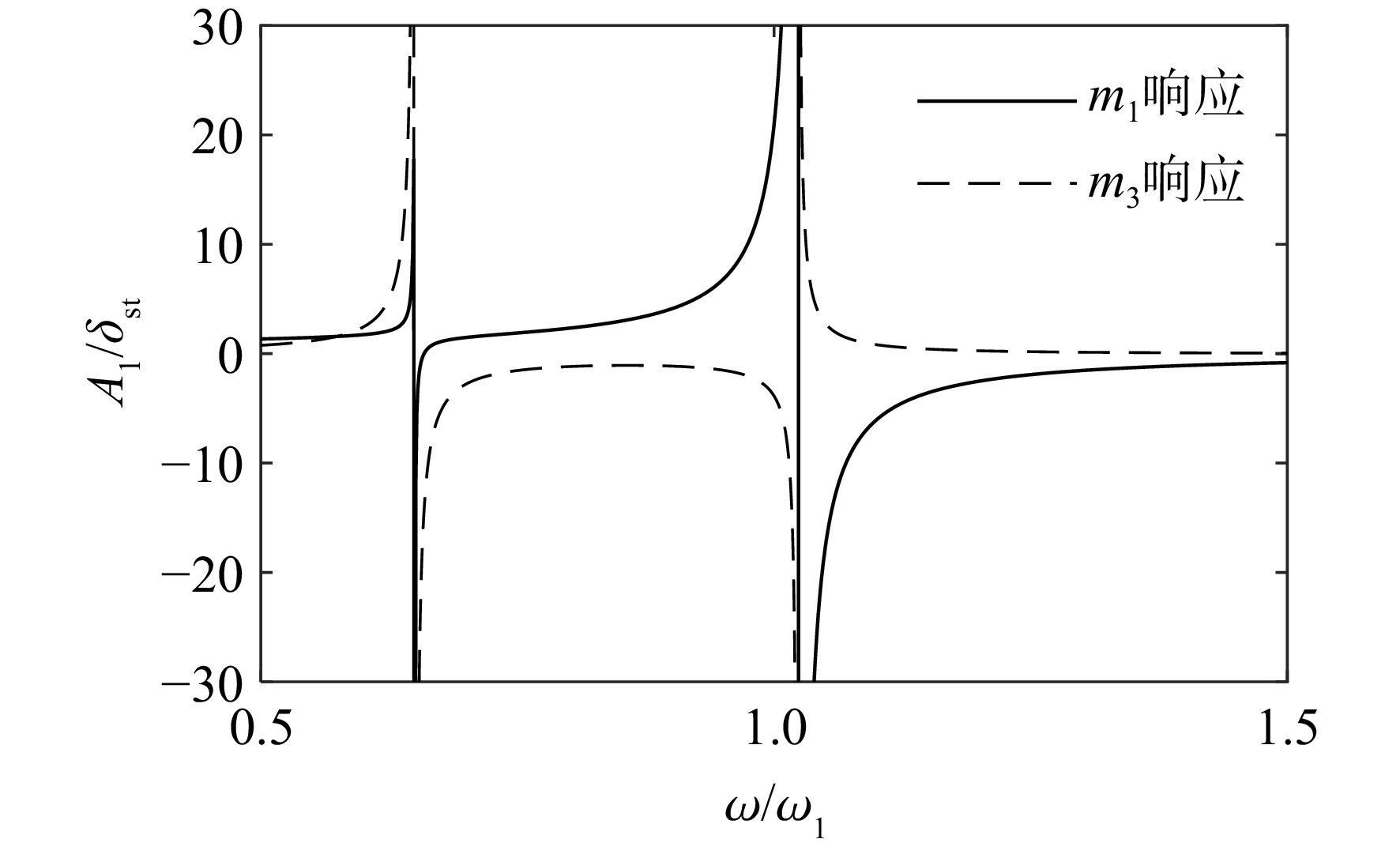
图 5 优化前振系0和振系1响应的对比
Figure 5. Vibration response of system 0 and system 1 before optimization

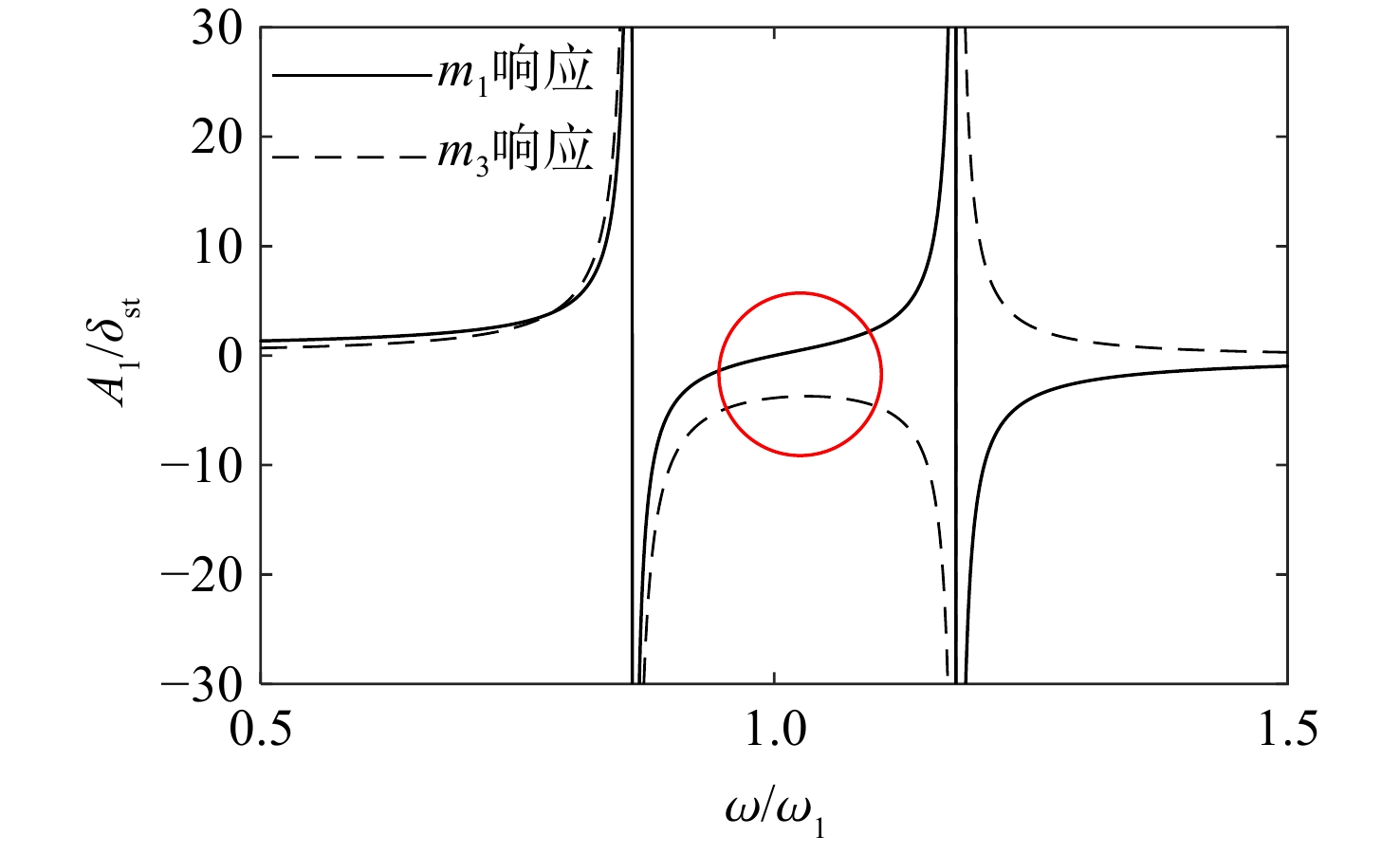
图 6 优化后振系0和振系1响应的对比
Figure 6. Vibration response of system 0 and system 1 after optimization

图 7 考虑相位时优化前振系0响应
Figure 7. Vibration response consider vibration phase of system 0 before optimization

图 8 考虑相位时优化后振系0响应
Figure 8. Vibration response consider vibration phase of system 0 after optimization

图 9 振系0激励源为$m_3 $时的情况
Figure 9. Structure of system 0 when the excitation source is particle $m_3 $

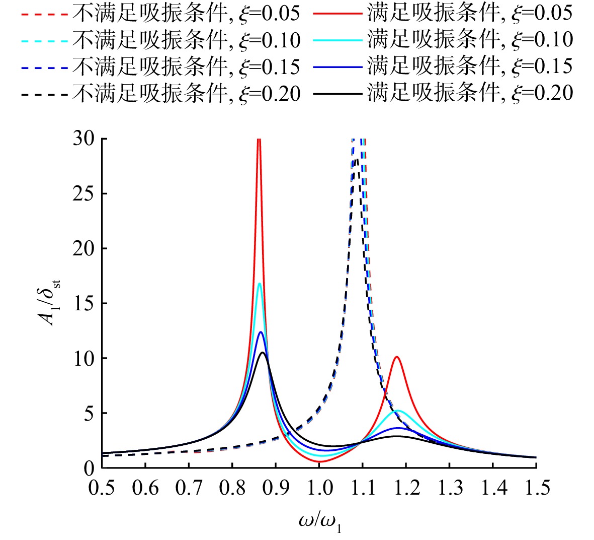
图 11 动力吸振对m1振动的抑制效果对比
Figure 11. Comparison of vibration suppression effect on m1 by dynamic vibration absorption

图 12 优化前后质量块$m_1 $响应随阻尼$c_3 $的变化
Figure 12. Change of $m_1 $ response with damping $c_3 $ before and after optimization

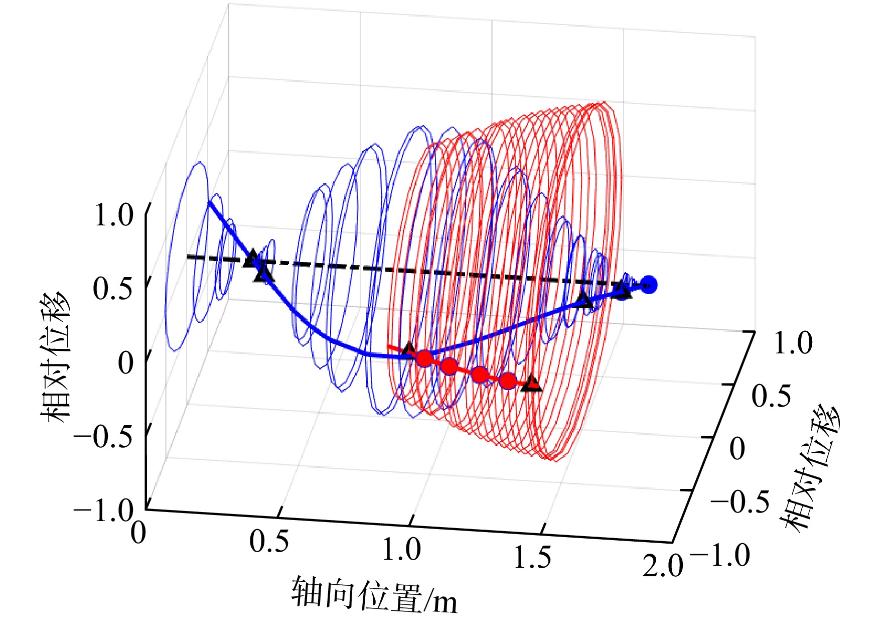
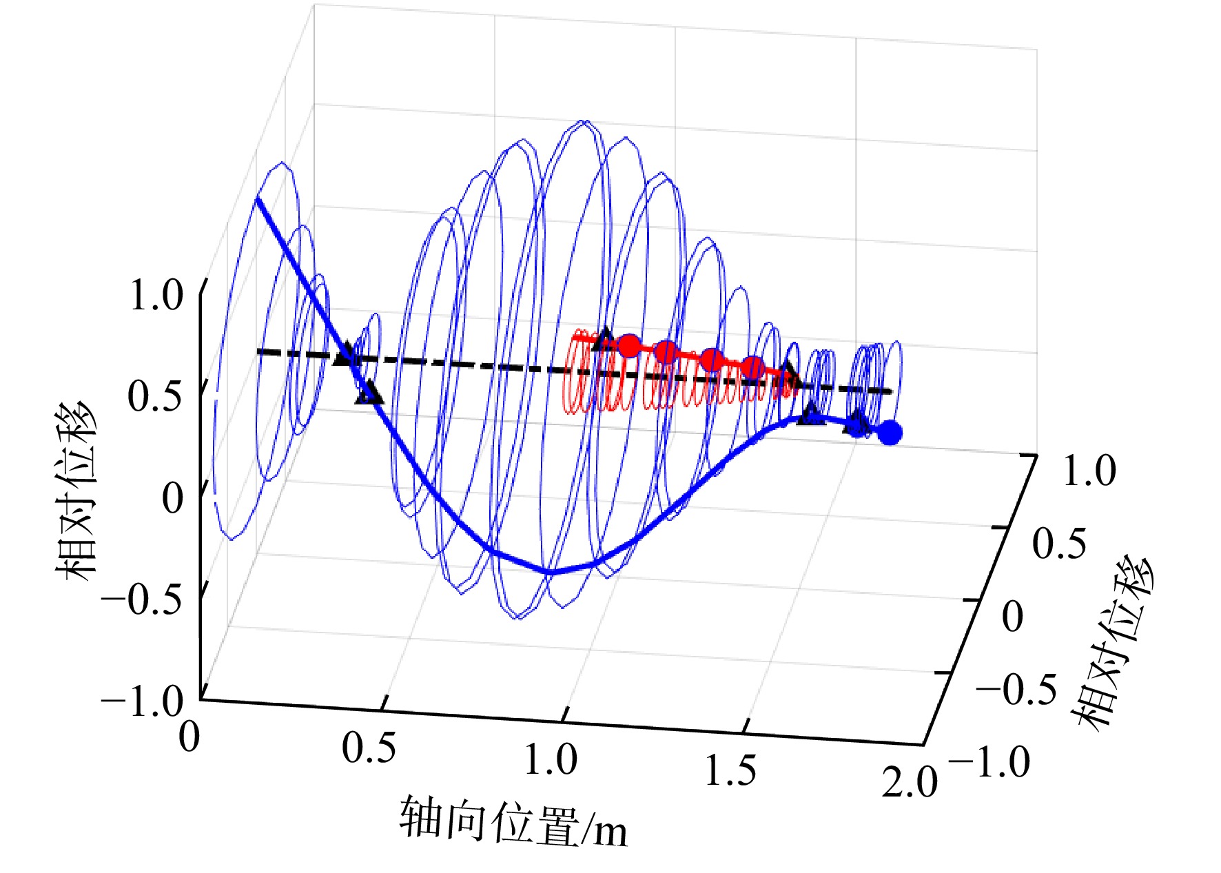
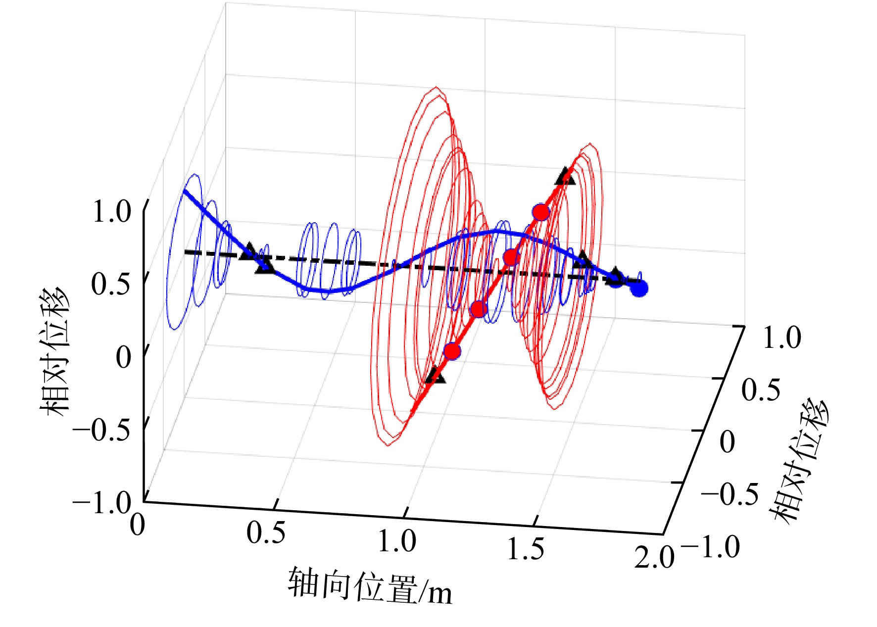
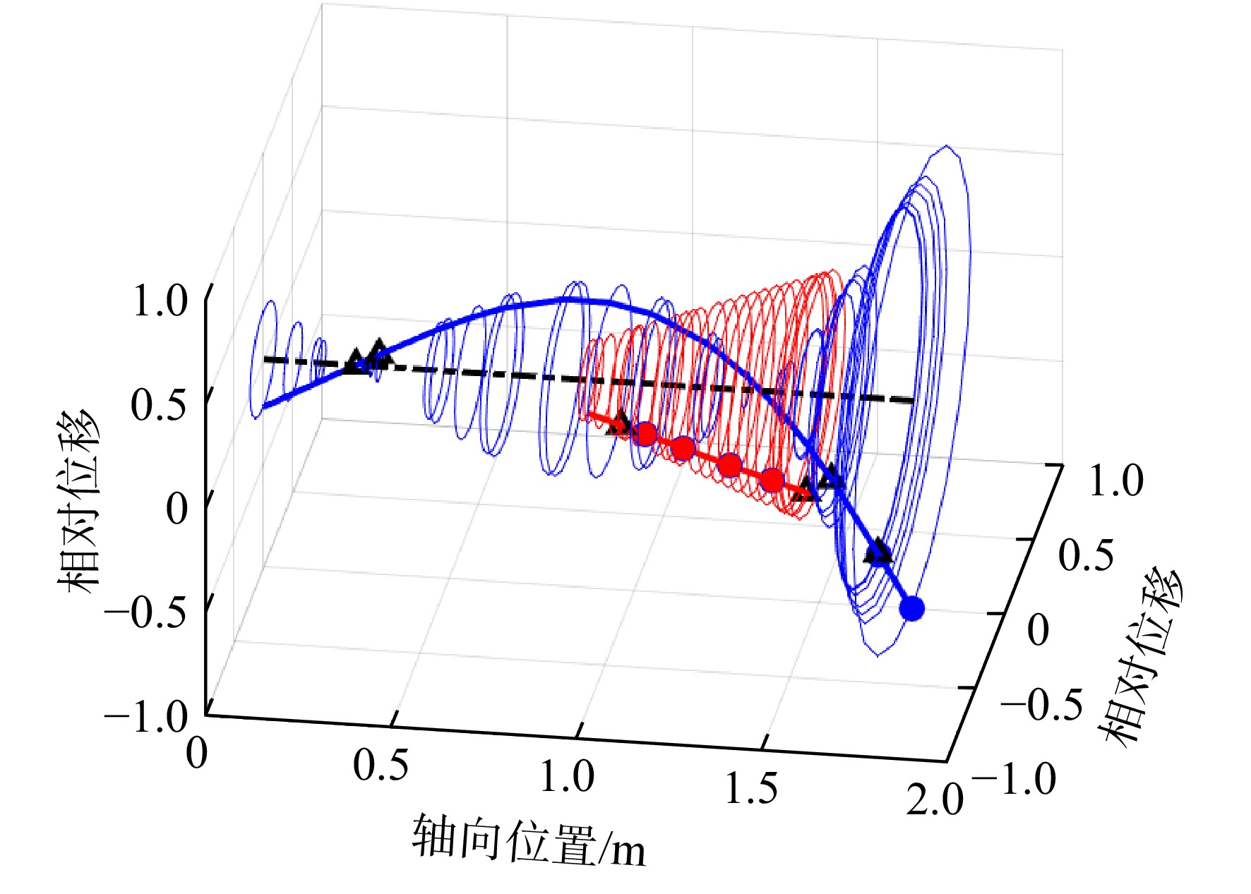
图 13 阻尼$c_3 $趋向于+∞时的振系结构(振系3)
Figure 13. Particle system with damper $c_3 $ tending to +∞ (system 3)

图 15 最优阻尼$c_3 $时质量块$m_1 $的不动点
Figure 15. Fixed point of $m_1 $ under the optimal damper $c_3 $

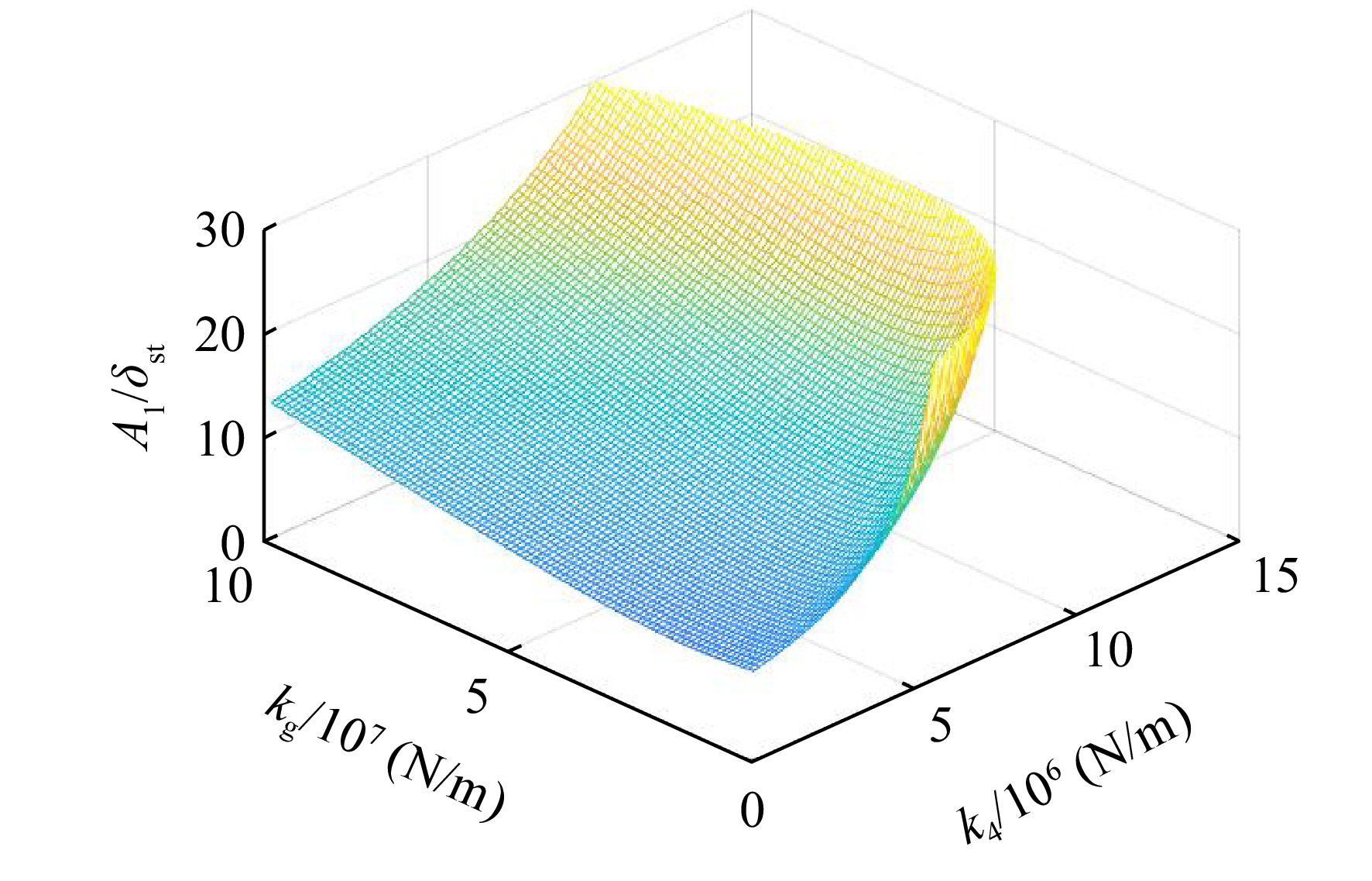
图 16 最大不动点处幅值随刚度组合$ k_{4} $和$ k_{\rm{g}} $的变化
Figure 16. Amplitude of the largest fixed point changes by different $ k_{4} $ and $ k_{\rm{g}} $ combinations

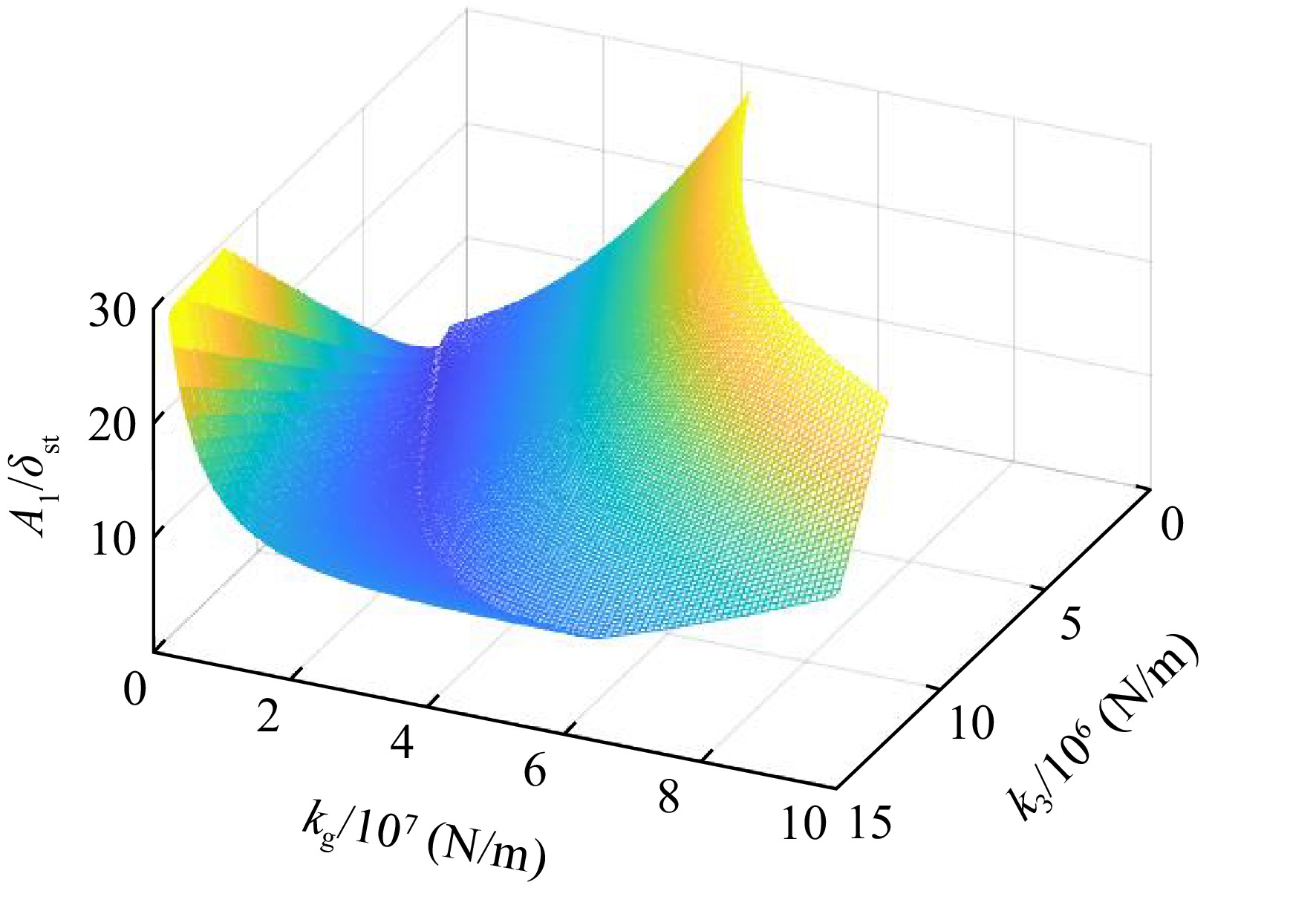
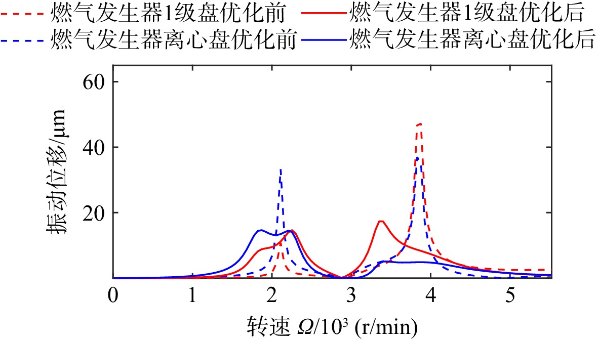
图 17 $ k_{4}=3 \times 10^{6}\; \mathrm{N} / \mathrm{m} $时不动点P2处幅值随刚度组合$ k_{\rm{g}} $和$ k_{3} $的变化
Figure 17. Amplitude of the fixed point P2 changes by different $ k_{\rm{g}} $ and $ k_{3} $ combinations when $ k_{4}=3 \times 10^{6}\; \mathrm{N} / \mathrm{m} $

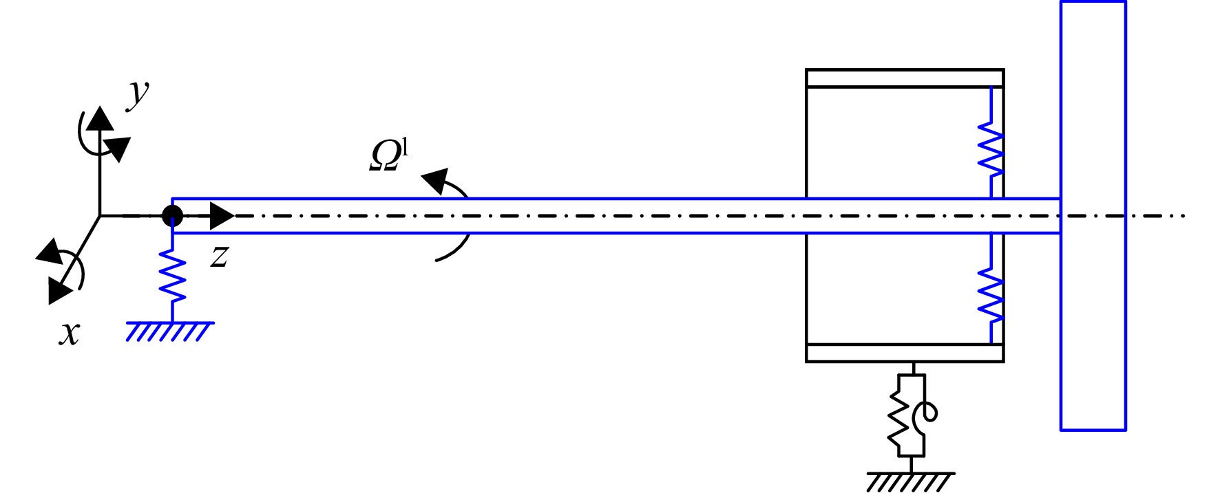
图 18 动力涡轮与共用支承结构构成的转子系统
Figure 18. Rotor system consist by power turbine and mid turbine frame

图 19 带有共用支承结构的双转子系统简化模型
Figure 19. Simplified model of dual rotor system with mid turbine frame

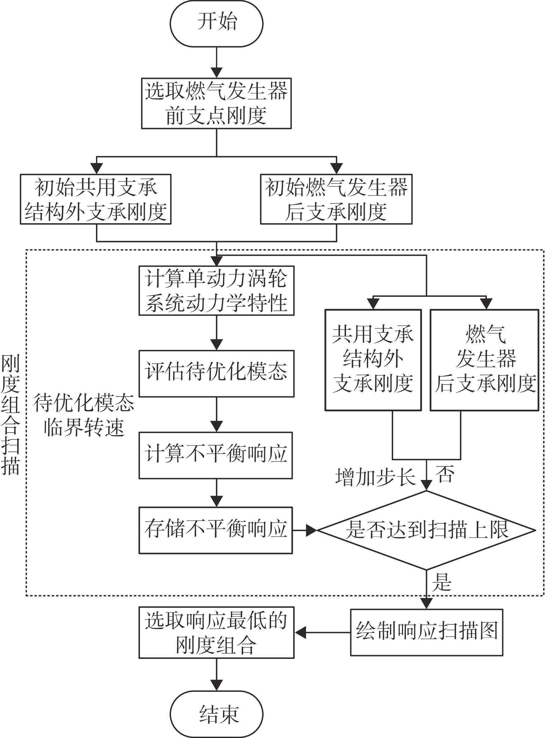
图 20 振能转移刚度优化流程图
Figure 20. Vibration energy transmission stiffness optimization flow chart

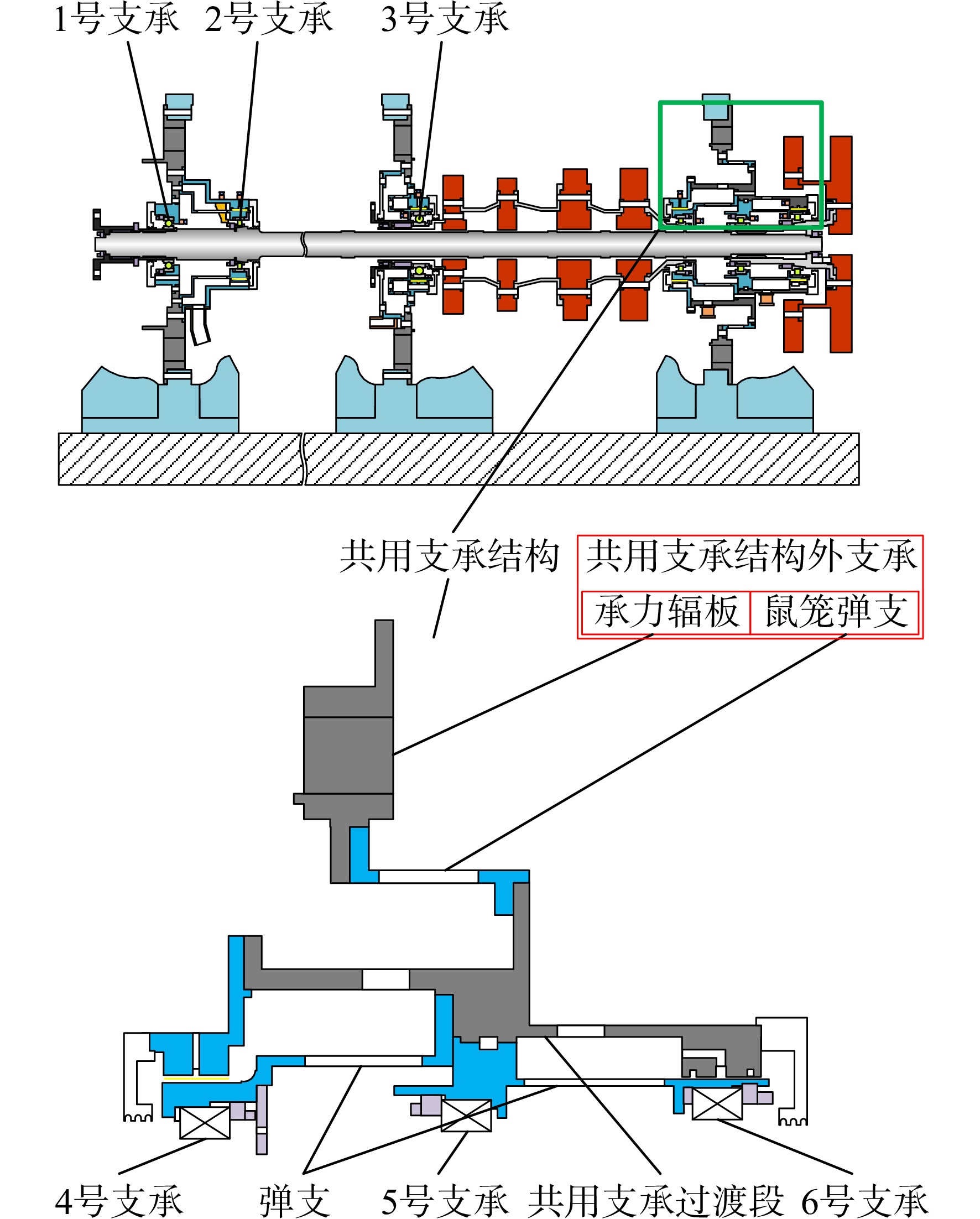
图 21 共用支承结构模拟双转子模型
Figure 21. Structure of the simulated dual rotor model with mid turbine frame

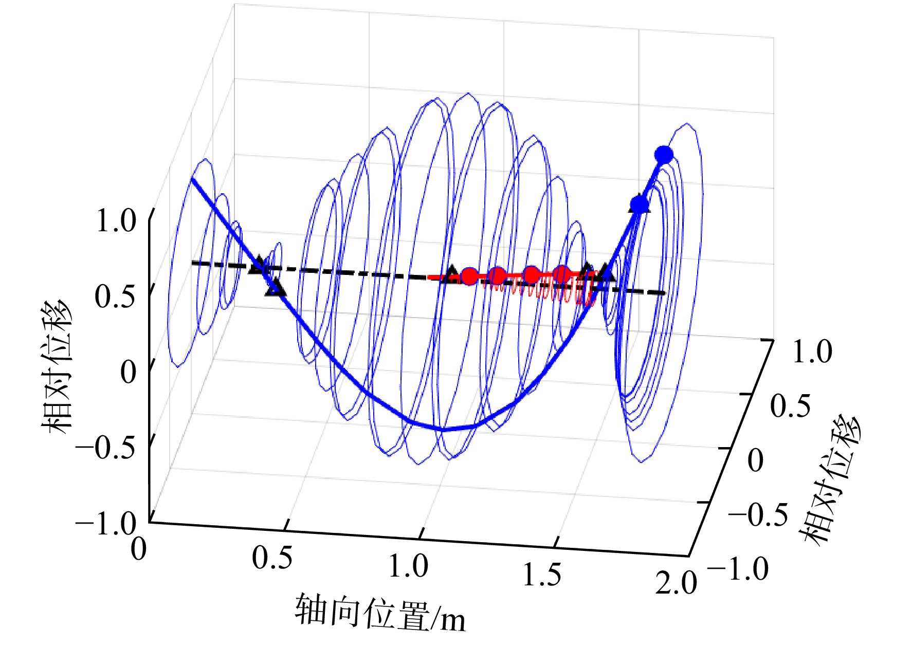
图 26 优化后动力涡轮自激励第1阶模态
Figure 26. The 1st-order power turbine self-excitation mode after the optimization

图 27 优化后燃气发生器自激励第1阶模态
Figure 27. The 1st-order gas generator self-excitation mode after the optimization

图 28 优化后动力涡轮自激励第2阶模态
Figure 28. The 2nd-order power turbine self-excitation mode after the optimization

图 29 优化后燃气发生器自激励第2阶模态
Figure 29. The 2nd-order gas generator self-excitation mode after the optimization

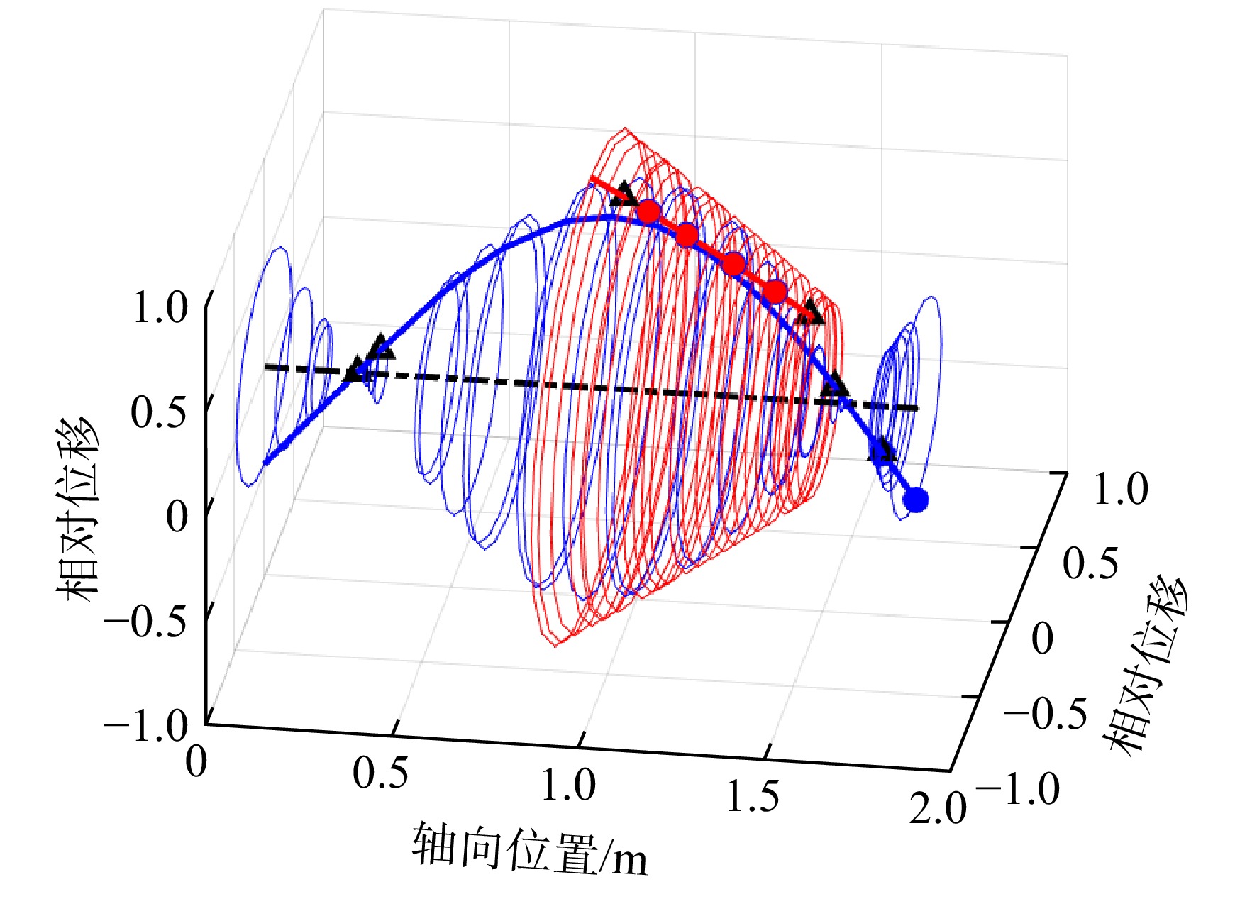
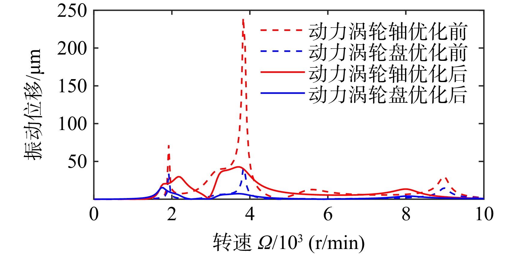
图 30 动力涡轮转子在自身激励下的不平衡响应
Figure 30. Power turbine’s unbalance response under its self-excitation

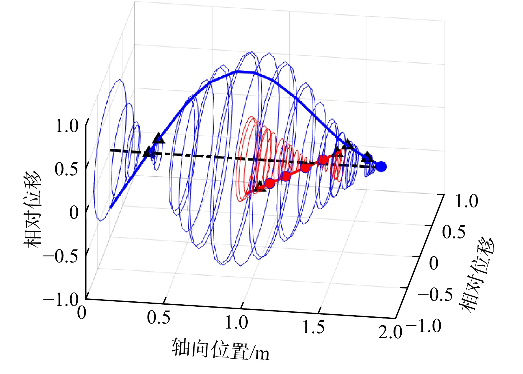
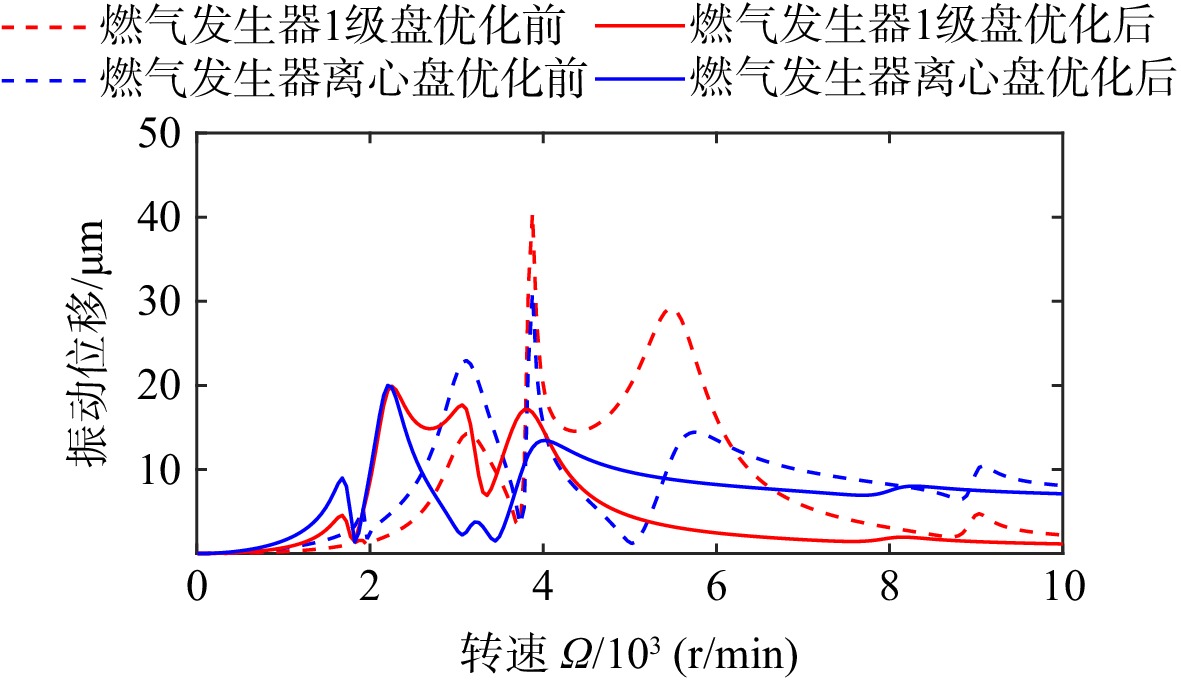
图 31 燃气发生器转子在动力涡轮转子激励下的不平衡响应
Figure 31. Gas generator’s unbalance response under the power turbine’s excitation

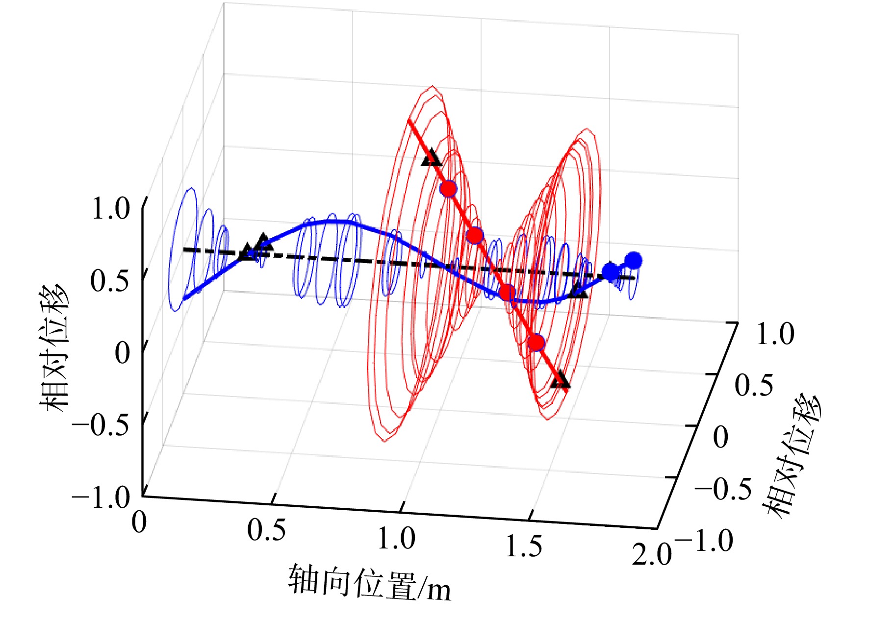
图 32 燃气发生器转子交叉激励下动力涡轮转子不平衡响应
Figure 32. Power turbine’s unbalance response under the gas generator’s excitation

图 33 燃气发生器转子自激励下燃气发生器不平衡响应
Figure 33. Gas generator’s unbalance response under its self-excitation

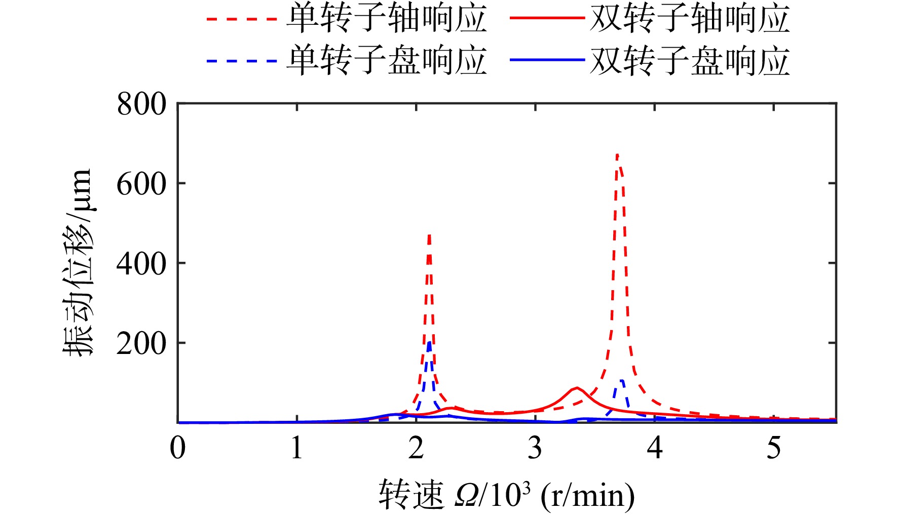
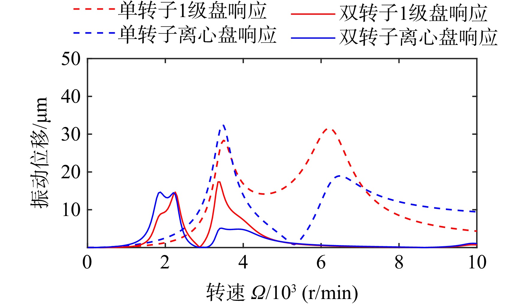
图 34 单独的动力涡轮转子和双转子不平衡响应对比
Figure 34. Comparison of unbalance response between the single power turbine and the dual rotor system

图 35 单独的燃气发生器转子和双转子不平衡响应对比
Figure 35. Comparison of unbalance response between the single gas generator and the dual rotor system
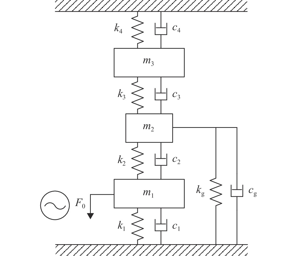
表 1 简化模型符号对照表
Table 1. Symbol comparison of the simplified model
参数 符号 动力涡轮前支承刚度 $ k_{1} $ 动力涡轮后支承刚度 $ k_{2} $ 燃气发生器后支承刚度 $ k_{3} $ 燃气发生器前支承刚度 $ k_{4} $ 外支承径向刚度 $ k_{{\mathrm{g}}} $ 动力涡轮前支承阻尼 $ c_{1} $ 动力涡轮后支承阻尼 $ c_{2} $ 燃气发生器后支承阻尼 $ c_{3} $ 燃气发生器前支承阻尼 $ c_{4} $ 外支承径向阻尼 $ c_{{\mathrm{g}}} $ 动力涡轮质量 $ m_{1} $ 共用支承结构质量 $ m_{2} $ 燃气发生器质量 $ m_{3} $ 动力涡轮激振力 $ F_{0} $  下载: 导出CSV
表 2 优化前后的无量纲参数
Table 2. Dimensionless parameters before and after the optimization
参数 优化前参数值 优化后参数值 $ \mu $ 2/3 2/3 $ S_{1} $ 0.5 0.5 $ S_{2} $ 1 1 $ S_{3} $ 0.3 0.6966 $ S_{4} $ 0.15 0.15 $ S_{\rm{g}} $ 1 1
下载: 导出CSV
表 3 模拟双转子模型转子支承参数
Table 3. Support parameters of the simulated dual rotor model
支承编号 支承位置 支承刚度/106 (N/m) 1 动力涡轮前支承刚支 100 2 动力涡轮前支承弹支 3.0 3 燃气发生器前支承 8.9 4 燃气发生器后支承 8.9 5 动力涡轮后支承刚支 100 6 动力涡轮后支点弹支 3.3 G 共用支承结构 54.1
下载: 导出CSV
表 4 模拟双转子模型轮盘节点信息
Table 4. Disk nodes of the simulated dual rotor model
名称 节点
编号质量/
kg直径转动惯量/
(kg·m2)极转动惯量/
(kg·m2)动力涡轮1级盘 37 25.15 0.33 0.66 动力涡轮2级盘 35 40.61 0.44 0.87 燃气发生器1级盘 44 15.36 0.07 0.14 燃气发生器2级盘 47 12.46 0.05 0.1 燃气发生器离心盘 51 26.14 0.14 0.26 燃气发生器2级盘 55 24.62 0.13 0.26
下载: 导出CSV
表 5 各阶自激励模态应变能占比
Table 5. Strain energy proportion of each self-excited mode
阶次 应变能占比/% 1号轴承 2号轴承 3号轴承 4号轴承 5号轴承 6号轴承 共用支承径向 共用支承角向 动力涡轮 燃气发生器 动力涡轮1阶 0.0031 1.8519 0.1363 0.1994 1.3403 26.924 11.870 0.0302 57.634 0.0104 燃气发生器1阶 0 0.5212 34.924 40.477 0.2637 0.4091 13.311 0.0033 8.0109 2.0788 动力涡轮2阶 0.0007 2.6493 7.9017 7.1104 7.7013 0.4531 11.853 0.0008 61.960 0.3694 燃气发生器2阶 0.3833 0.1947 44.935 22.340 0.0910 0.5178 7.8110 0.0015 17.321 6.4041
下载: 导出CSV
表 6 优化前后支承刚度
Table 6. Supports stiffness before and after optimization
编号 支承位置 径向刚度/106 (N/m) 优化前 优化后 1 动力涡轮前支承刚支 100 100 2 动力涡轮前支承弹支 3 3 3 燃气发生器前支承 8.9 3 4 燃气发生器后支承 8.9 8 5 动力涡轮后支承刚支 100 100 6 动力涡轮后支点弹支 3.3 3.3 G 共用支承结构 54.1 10
下载: 导出CSV
表 7 优化前后自激励模态临界转速
Table 7. Critical speed before and after optimization
阶次 临界转速/(r/min) 优化前 优化后 动力涡轮1阶 2471 1950 燃气发生器1阶 3932 2717 动力涡轮2阶 4972 4056 燃气发生器2阶 8461 6473
下载: 导出CSV
表 8 优化后应变能分布情况
Table 8. Strain energy proportion after the optimization
阶次 应变能占比/% 1号轴承 2号轴承 3号轴承 4号轴承 5号轴承 6号轴承 共用支承径向 共用支承角向 动力涡轮 燃气发生器 动力涡轮1阶 0.0034 0.5386 2.2907 1.4249 0.7432 18.077 43.538 0.0186 33.307 0.0587 燃气发生器1阶 0.0003 0.8437 53.336 16.340 0.0005 5.2912 6.4647 0.0096 16.895 0.8177 动力涡轮2阶 0.0001 2.8803 24.054 0.3191 2.6620 1.8518 25.920 0.0021 42.186 0.1246 燃气发生器2阶 0.0062 0.6589 18.980 43.744 2.1957 1.4450 2.9146 0.0041 28.711 1.3406
下载: 导出CSV
-
[1] KUMAR K B,SOMANATH N,SOWA W A. Mid-turbine frame: US8181466[P]. 2012-05-22. [2] 马艳红,曹冲,李鑫,等. 涡轴发动机涡轮级间支承结构设计关键技术[J]. 航空发动机,2014,40(4): 34-40. MA Yanhong,CAO Chong,LI Xin,et al. Key design technology of mid turbine frame for turboshaft engine[J]. Aeroengine,2014,40(4): 34-40. (in ChineseMA Yanhong, CAO Chong, LI Xin, et al. Key design technology of mid turbine frame for turboshaft engine[J]. Aeroengine, 2014, 40(4): 34-40. (in Chinese) [3] 雷冰龙,李超,何康,等. 共用支承-转子系统耦合振动分析及试验[J]. 航空动力学报,2020,35(11): 2293-2305. LEI Binglong,LI Chao,HE Kang,et al. Coupling vibration characteristics analysis and experiment of shared support-rotors system[J]. Journal of Aerospace Power,2020,35(11): 2293-2305. (in ChineseLEI Binglong, LI Chao, HE Kang, et al. Coupling vibration characteristics analysis and experiment of shared support-rotors system[J]. Journal of Aerospace Power, 2020, 35(11): 2293-2305. (in Chinese) [4] 陈予恕,张华彪. 航空发动机整机动力学研究进展与展望[J]. 航空学报,2011,32(8): 1371-1391. CHEN Yushu,ZHANG Huabiao. Review and prospect on the research of dynamics of complete aero-engine systems[J]. Acta Aeronautica et Astronautica Sinica,2011,32(8): 1371-1391. (in ChineseCHEN Yushu, ZHANG Huabiao. Review and prospect on the research of dynamics of complete aero-engine systems[J]. Acta Aeronautica et Astronautica Sinica, 2011, 32(8): 1371-1391. (in Chinese) [5] 邓旺群,王桢,舒斯荣,等. 涡轴发动机细长柔性转子动力特性及高速动平衡技术研究[J]. 振动与冲击,2012,31(7): 162-165,170. DENG Wangqun,WANG Zhen,SHU Sirong,et al. Dynamic characteristics and high speed dynamic balance technique for a power turbine rotor of a turbo-shaft engine[J]. Journal of Vibration and Shock,2012,31(7): 162-165,170. (in Chinese doi: 10.3969/j.issn.1000-3835.2012.07.034DENG Wangqun, WANG Zhen, SHU Sirong, et al. Dynamic characteristics and high speed dynamic balance technique for a power turbine rotor of a turbo-shaft engine[J]. Journal of Vibration and Shock, 2012, 31(7): 162-165, 170. (in Chinese) doi: 10.3969/j.issn.1000-3835.2012.07.034 [6] SINGIRESU S R. 机械振动[M]. 李欣业,杨理成,译. 第5版. 北京: 清华大学出版社,2016. SINGIRESU S R. Mechanical vibrations[M]. LI Xinye,YANG Licheng,translated. 5th. ed. Beijing: Tsinghua University Press,2016. (in ChineseSINGIRESU S R. Mechanical vibrations[M]. LI Xinye, YANG Licheng, translated. 5th. ed. Beijing: Tsinghua University Press, 2016. (in Chinese) [7] 邓旺群,高德平. 涡轴发动机动力涡轮转子高速动平衡技术研究[J]. 航空动力学报,2003,18(5): 669-675. DENG Wangqun,GAO Deping. High speed dynamic balance technique of a power turbine rotor of a turbine shaft engine[J]. Journal of Aerospace Power,2003,18(5): 669-675. (in Chinese doi: 10.3969/j.issn.1000-8055.2003.05.017DENG Wangqun, GAO Deping. High speed dynamic balance technique of a power turbine rotor of a turbine shaft engine[J]. Journal of Aerospace Power, 2003, 18(5): 669-675. (in Chinese) doi: 10.3969/j.issn.1000-8055.2003.05.017 [8] 唐振寰,米栋,卢愈,等. 轴承共腔-双转子系统耦合振动特性研究[J]. 推进技术,2022,43(2): 210566. TANG Zhenhuan,MI Dong,LU Yu,et al. Coupling vibration characteristics for shared bearing bore-coaxial rotor system[J]. Journal of Propulsion Technology,2022,43(2): 210566. (in ChineseTANG Zhenhuan, MI Dong, LU Yu, et al. Coupling vibration characteristics for shared bearing bore-coaxial rotor system[J]. Journal of Propulsion Technology, 2022, 43(2): 210566. (in Chinese) [9] 韩军,高德平,胡绚,等. 航空发动机双转子系统的拍振分析[J]. 航空学报,2007,28(6): 1369-1373. HAN Jun,GAO Deping,HU Xuan,et al. Research on beat vibration of dual-rotor for aero-engine[J]. Acta Aeronautica et Astronautica Sinica,2007,28(6): 1369-1373. (in Chinese doi: 10.3321/j.issn:1000-6893.2007.06.017HAN Jun, GAO Deping, HU Xuan, et al. Research on beat vibration of dual-rotor for aero-engine[J]. Acta Aeronautica et Astronautica Sinica, 2007, 28(6): 1369-1373. (in Chinese) doi: 10.3321/j.issn:1000-6893.2007.06.017 [10] 洪杰,杨振川,王永锋,等. 航空发动机承力结构隔振设计方法及试验[J]. 北京航空航天大学学报,2019,45(1): 10-17. HONG Jie,YANG Zhenchuan,WANG Yongfeng,et al. Vibration isolation design method and experiment of aero-engine supporting structure[J]. Journal of Beijing University of Aeronautics and Astronautics,2019,45(1): 10-17. (in ChineseHONG Jie, YANG Zhenchuan, WANG Yongfeng, et al. Vibration isolation design method and experiment of aero-engine supporting structure[J]. Journal of Beijing University of Aeronautics and Astronautics, 2019, 45(1): 10-17. (in Chinese) [11] TAN T H,LEE H P,LENG G S B. Dynamic stability of a radially rotating beam subjected to base excitation[J]. Computer Methods in Applied Mechanics and Engineering,1997,146(3/4): 265-279. [12] DUCHEMIN M,BERLIOZ A,FERRARIS G. Dynamic behavior and stability of a rotor under base excitation[J]. Journal of Vibration and Acoustics,2006,128(5): 576-585. doi: 10.1115/1.2202159 [13] 张欢. 考虑基础运动的转子系统动力学特性分析[D]. 哈尔滨: 哈尔滨工业大学,2014. ZHANG Huan. Dynamic characteristics analysis of rotor system considering basic motion[D]. Harbin: Harbin Institute of Technology,2014. (in ChineseZHANG Huan. Dynamic characteristics analysis of rotor system considering basic motion[D]. Harbin: Harbin Institute of Technology, 2014. (in Chinese) [14] 陈曦. 基础运动激励条件下转子系统动力学特性研究[D]. 西安: 西北工业大学,2019. CHEN Xi. Study on dynamic characteristics of rotor system under the excitation of basic motion[D]. Xi’an: Northwestern Polytechnical University,2019. (in ChineseCHEN Xi. Study on dynamic characteristics of rotor system under the excitation of basic motion[D]. Xi’an: Northwestern Polytechnical University, 2019. (in Chinese) [15] ORMONDROYD J,DEN HARTOG J P. The theory of the dynamic vibration absorber[J]. Transactions of the American Society of Mechanical Engineers,1928,49/50(2): 9-22. [16] REN M Z. A variant design of the dynamic vibration absorber[J]. Journal of Sound Vibration,2001,245(4): 762-770. doi: 10.1006/jsvi.2001.3564 [17] 郝岩,申永军,杨绍普,等. 含负刚度器件的Maxwell 模型动力吸振器的参数优化[J]. 振动与冲击,2019,38(4): 20-25. HAO Yan,SHEN Yongjun,YANG Shaopu,et al. Parameter optimization of a Maxwell model dynamic absorber with negative stiffness device[J]. Journal of Vibration and Shock,2019,38(4): 20-25. (in ChineseHAO Yan, SHEN Yongjun, YANG Shaopu, et al. Parameter optimization of a Maxwell model dynamic absorber with negative stiffness device[J]. Journal of Vibration and Shock, 2019, 38(4): 20-25. (in Chinese) [18] 周荣亚. 悬臂梁式动力吸振器多频减振研究[J]. 噪声与振动控制,2017,37(4): 197-200. ZHOU Rongya. Vibration reduction effect of cantilever type vibration absorbers in multi-frequency band[J]. Noise and Vibration Control,2017,37(4): 197-200. (in Chinese doi: 10.3969/j.issn.1006-1355.2017.04.039ZHOU Rongya. Vibration reduction effect of cantilever type vibration absorbers in multi-frequency band[J]. Noise and Vibration Control, 2017, 37(4): 197-200. (in Chinese) doi: 10.3969/j.issn.1006-1355.2017.04.039 [19] 背户一登. 动力吸振器及其应用[M]. 任明章,译. 北京: 机械工业出版社,2013. KAZUTO S. Dynamic vibration absorber and its applications[M]. REN Mingzhang,translated. Beijing: China Machine Press,2013. (in ChineseKAZUTO S. Dynamic vibration absorber and its applications[M]. REN Mingzhang, translated. Beijing: China Machine Press, 2013. (in Chinese) [20] 廖明夫. 航空发动机转子动力学[M]. 西安: 西北工业大学出版社,2015. LIAO Mingfu. Rotor dynamics of aero-engine[M]. Xi’an: Northwestern Polytechnical University Press,2015. (in ChineseLIAO Mingfu. Rotor dynamics of aero-engine[M]. Xi’an: Northwestern Polytechnical University Press, 2015. (in Chinese) -





 点击查看大图

计量
- 文章访问数: 408
- HTML浏览量: 295
- PDF量: 47
- 被引次数: 0