






Experimental and numerical study on flow and heat transfer characteristics of composite structure with impingement perforated plate and pin-fins
-
摘要:
实验和数值研究了涡轮叶片尾缘内部冷却通道中冲击孔板与扰流柱组合结构的流动和传热特性。扰流柱叉排地布置在叶片尾缘端面上。冲击孔板穿孔率为0.07~0.44,冲击距为1.5~4,基于进气通道水利直径和平均速度的雷诺数为1 600~4 000。采用瞬态液晶传热测量技术获得了柱肋通道壁面的局部表面传热系数分布,并分析了冲击孔板穿孔率、冲击距、雷诺数对柱肋通道流动结构以及表面传热特性的影响。研究结果表明:较小的穿孔率下形成的强烈冲击射流能够显著提升组合结构的平均传热性能,但是会极大地增加其流动损失;冲击距和穿孔率对冲击-扰流柱组合冷却结构的传热和压损特性具有显著的影响;组合冷却结构的传热性能是光滑通道传热性能的2.0~9.4倍,而其摩擦因数是光滑通道摩擦因数的136~1 800倍;获得了组合结构的强化传热因子与相关参数的实验关联式。
Abstract:The flow and heat transfer characteristics of the composite structure with impingement perforated plate and pin-fins in the cooling channel at the trailing edge of a turbine blade were experimentally and numerically studied. The pin-fins in a staggered array were arranged on the end face of the trailing edge. The perforation ratio varied between 0.07 and 0.44, and the jet-to-surface varied from 1.5 to 4. Reynolds number, based on the hydraulic diameter of the inlet channel, was tested within the range values from 1 600 to 4 000. The convective heat transfer coefficient distribution of the surface in the pin-fin channel was obtained by using the transient liquid crystal temperature measurement technique. The effects of perforated ratio and impingement distance on the flow structure and convective heat transfer characteristics of the pin-fin channel were analyzed. The results showed that the average heat transfer of the composite structure can be significantly improved by the strong impingement jet formed at a small perforation rate, but could greatly increase the flow loss. The impingement distance and perforation rate had a significant influence on the heat transfer and pressure loss characteristics of the impingement and pin-fin composite structure. The Nusselt number of the composite structure was 2.0—9.4 times that of the smooth channel, with a friction factor of 136—1 800 times that of the smooth channel. The experimental correlations between heat transfer enhancement factors and key parameters of the combined structure were obtained.
-

图 2 冲击扰流冷却结构示意图
Figure 2. Schematic diagram of cooling structures with jet impingement and pins
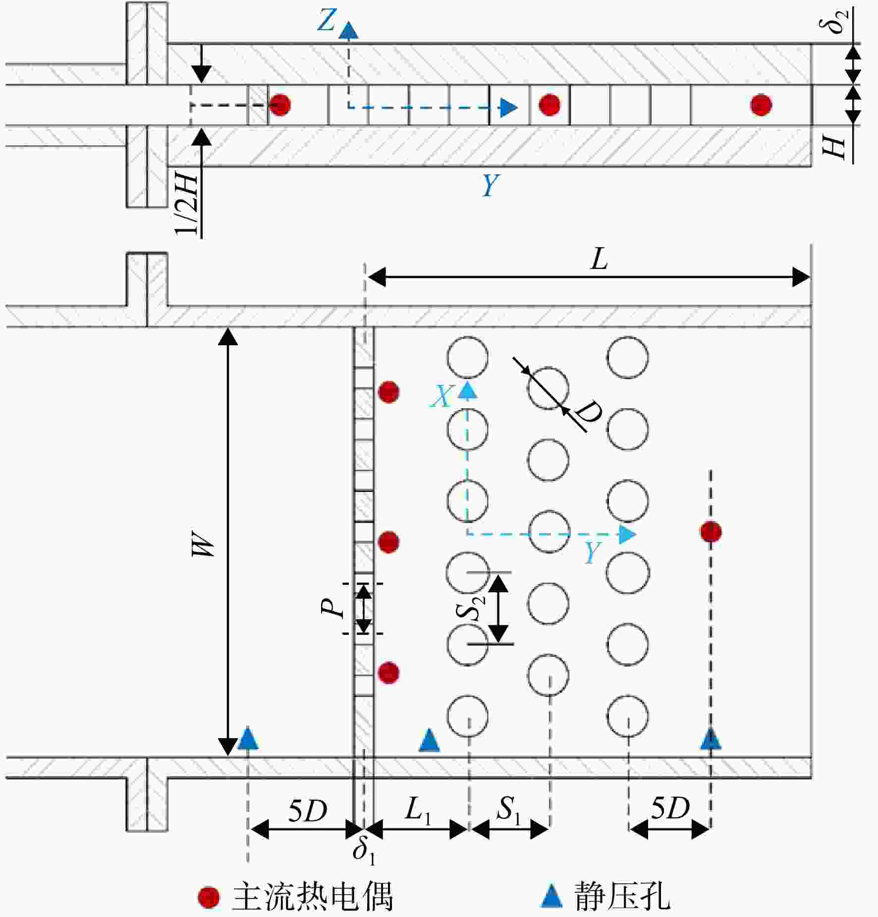
图 3 冲击柱肋通道测试段结构示意图
Figure 3. Schematic diagram of test section of impingement/pin-fin composite structure
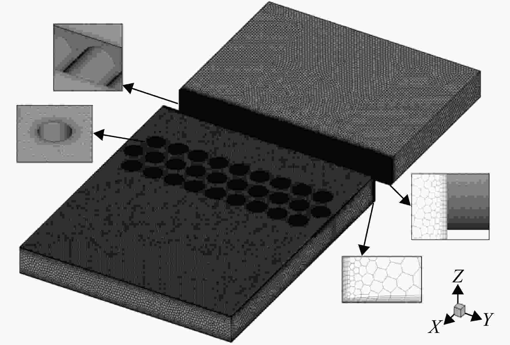
图 5 计算区域多面体网格划分和局部网格结构示意图
Figure 5. Schematic diagram of polyhedral grid of computational domain and local grid structure
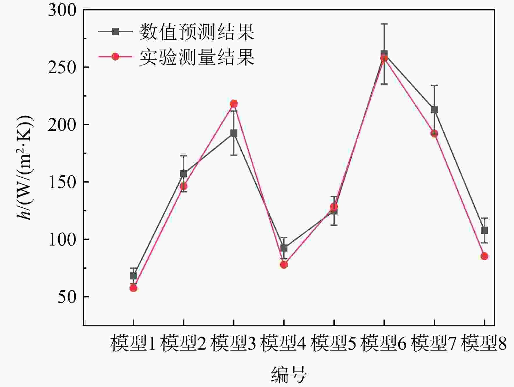
图 6 Re =
2800 时各个模型在柱肋通道扰流柱上游区域面积平均表面传热系数实验与数值对比Figure 6. Сomparison of experimental and numerical area-averaged heat transfer coefficient of each case at upper region of the pin-fin channel at Re =
2800 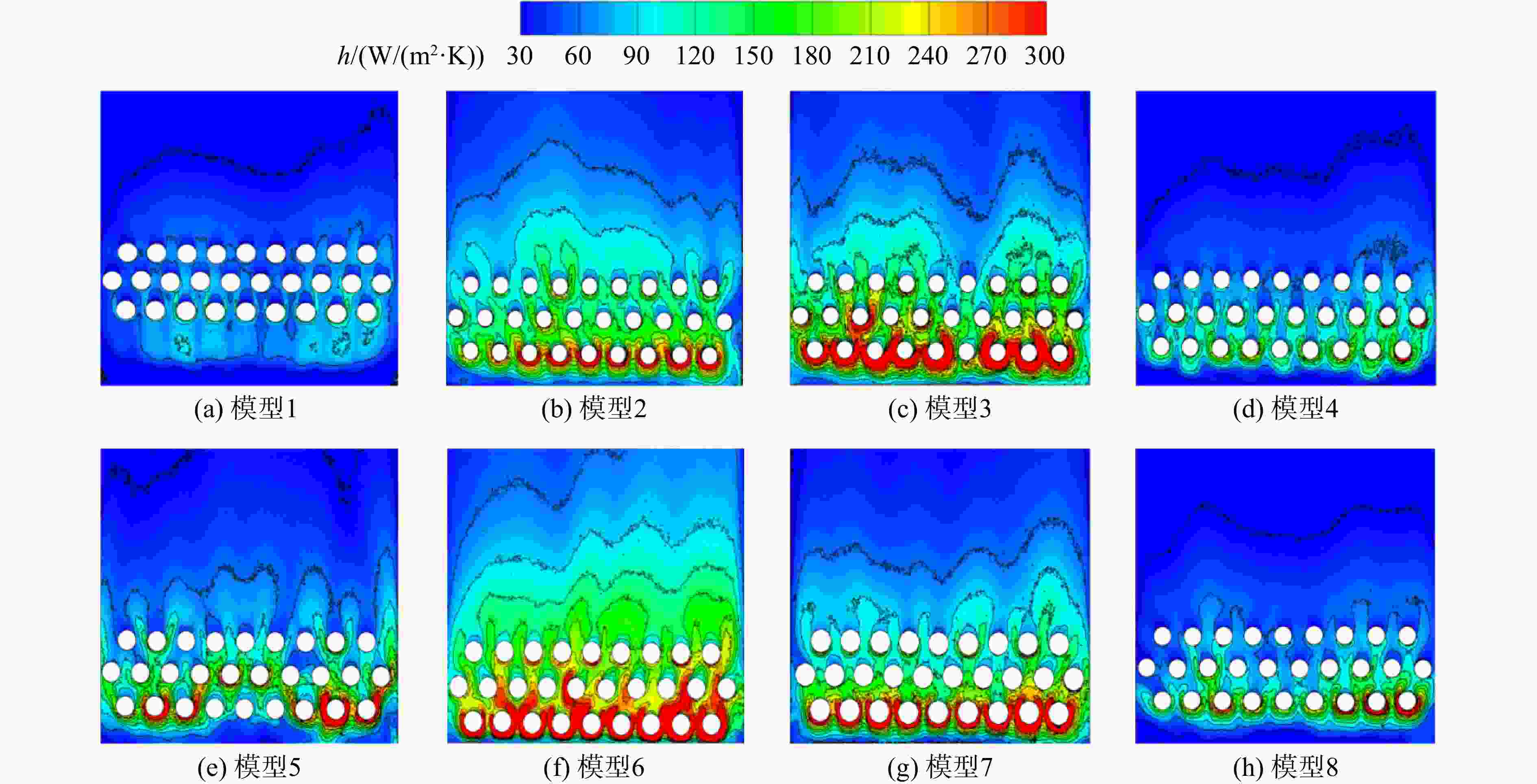
图 7 Re =
2800 时不同模型扰流柱通道壁面表面传热系数分布Figure 7. Distribution of local convective heat transfer coefficients on end wall of pin-fin channel for different cases at Re =
2800 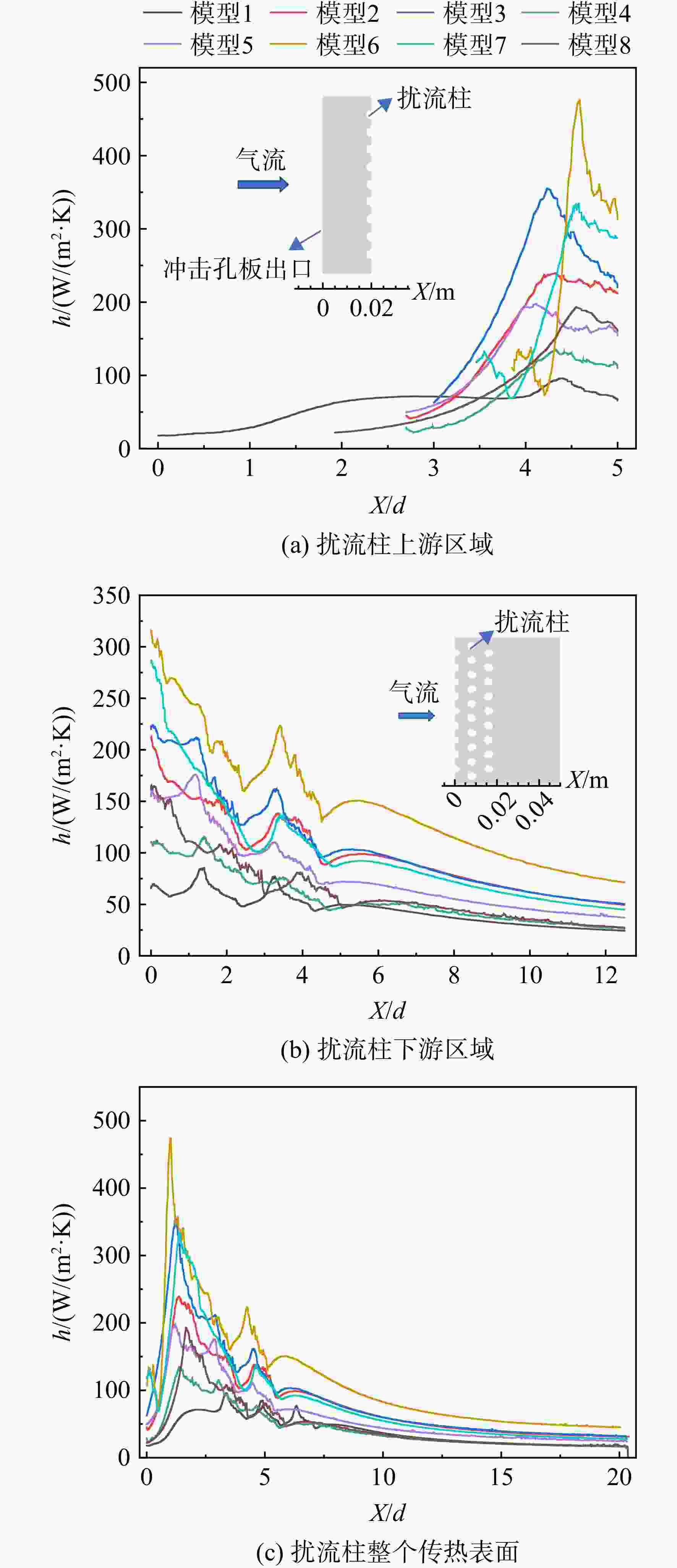
图 8 Re =
2800 时不同模型展向平均表面传热系数分布Figure 8. Distribution of spanwise-averaged convective heat transfer coefficients of different cases at Re =
2800 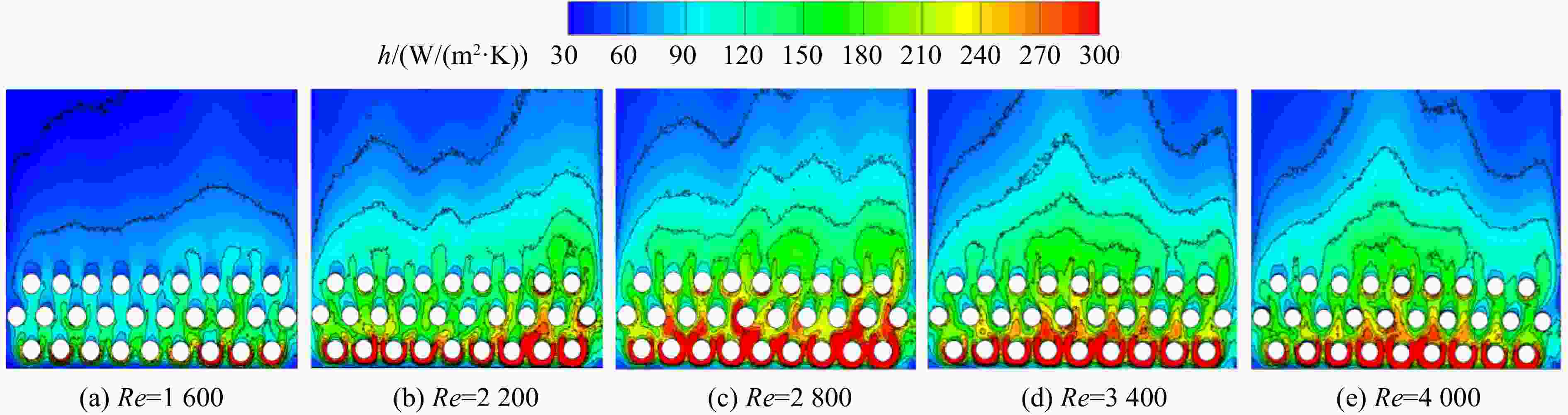
图 9 模型6柱面端面表面传热系数分布随雷诺数变化
Figure 9. Variation of distribution of convective heat transfer coefficient on end wall of pin-fin channel for Case 6 with Reynolds number
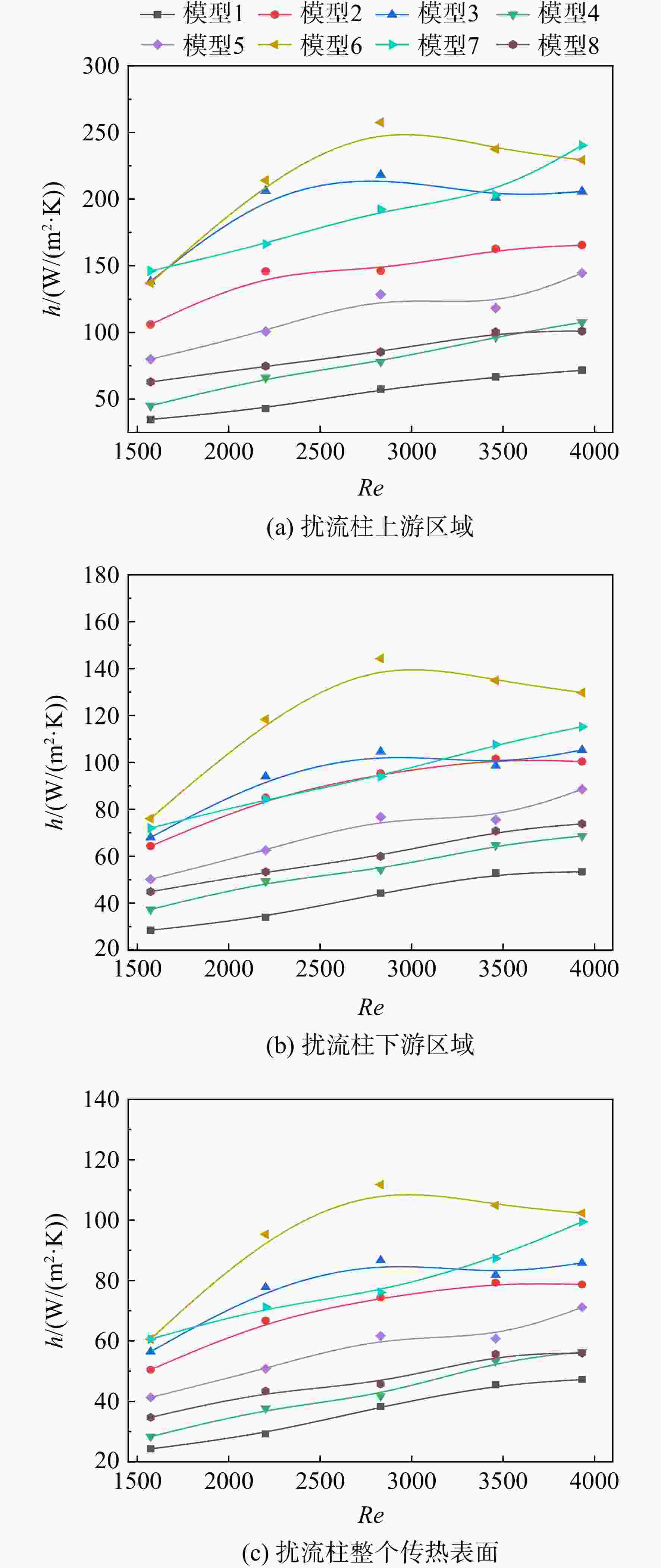
图 10 不同模型的面积平均表面传热系数分布
Figure 10. Aera-averaged convective heat transfer coefficient distribution with different cases
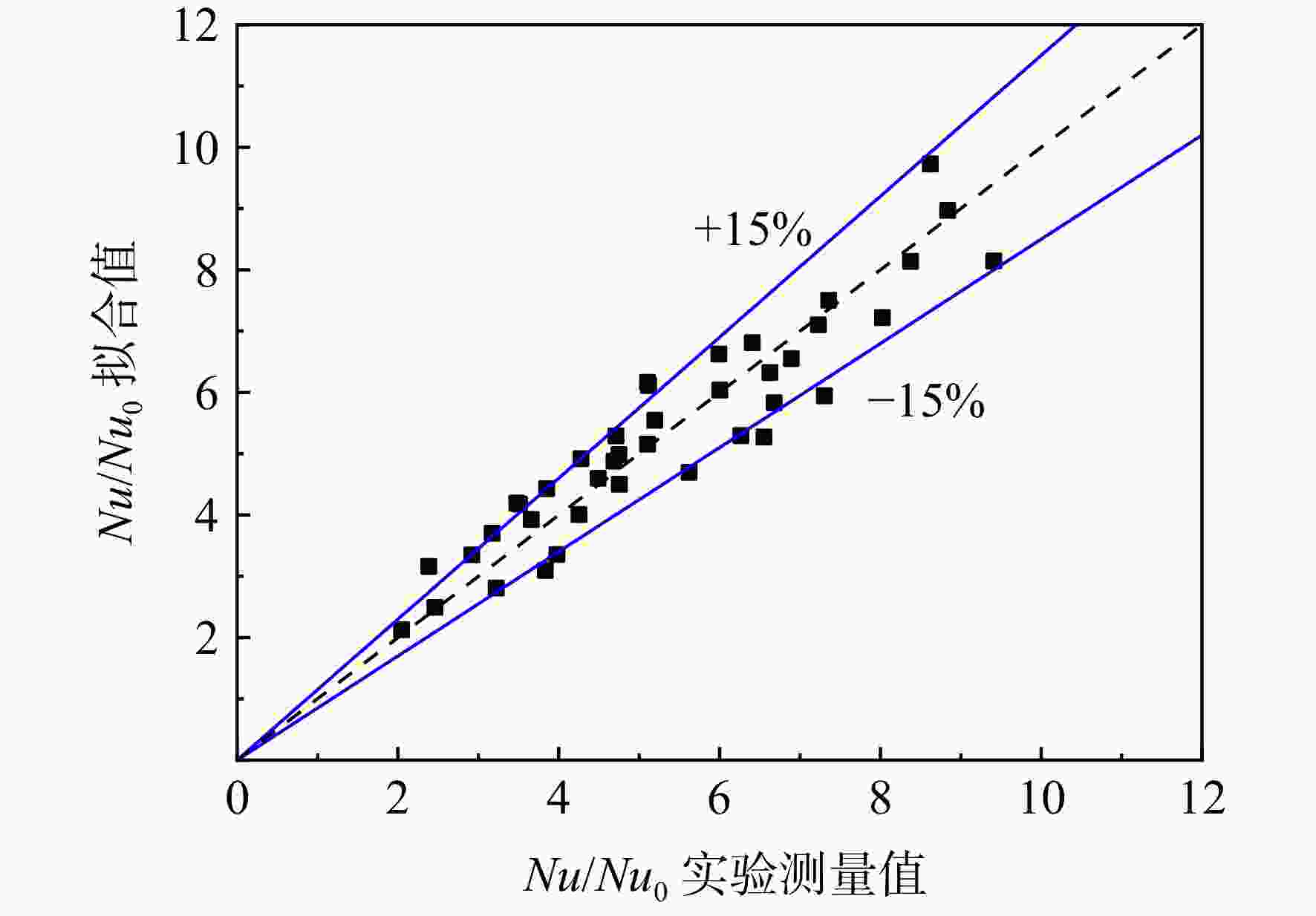
图 11 冲击扰流组合结构的强化传热因子的实验值与拟合值的比较
Figure 11. Comparison between experimental value and fitting value of heat transfer enhancement factor of composite structure with jet holes and pin-fins
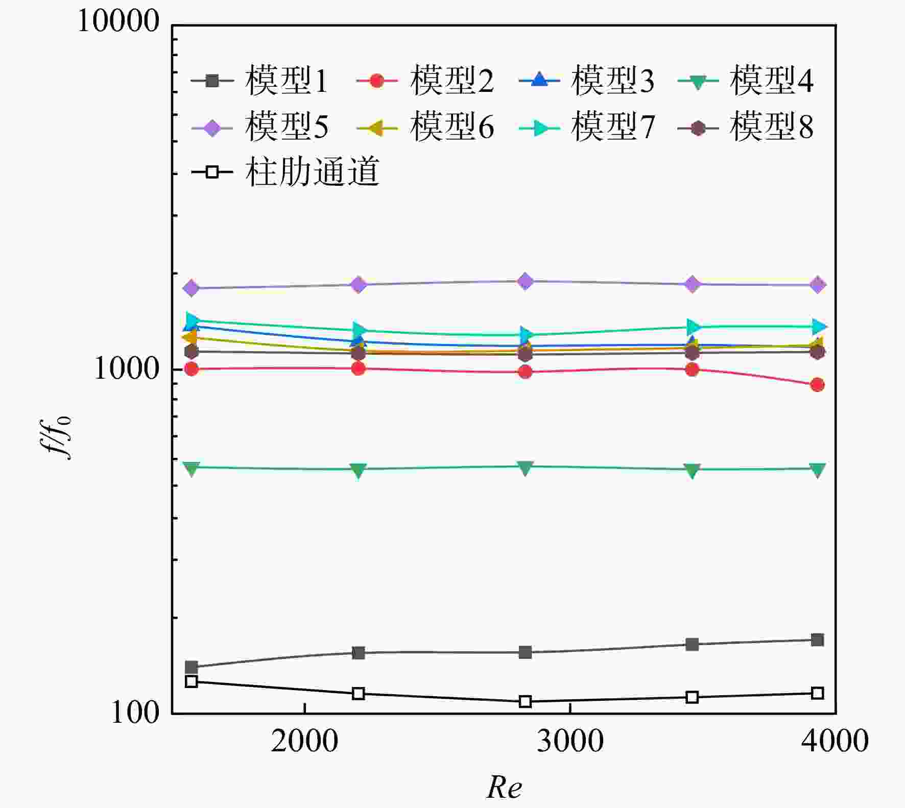
图 12 相对摩擦因数随雷诺数的变化
Figure 12. Variation of relative friction factor with Reynolds number
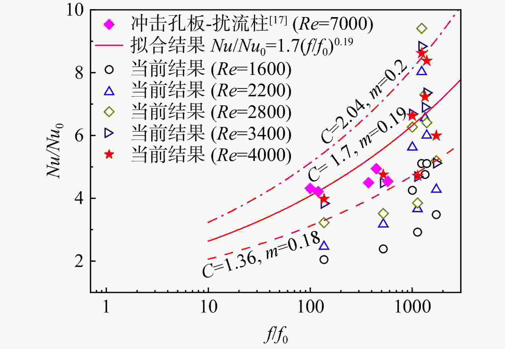
图 13 强化传热因子与相对摩擦因数之间的关系
Figure 13. Relationship between heat transfer enhancement factor and relative friction factor
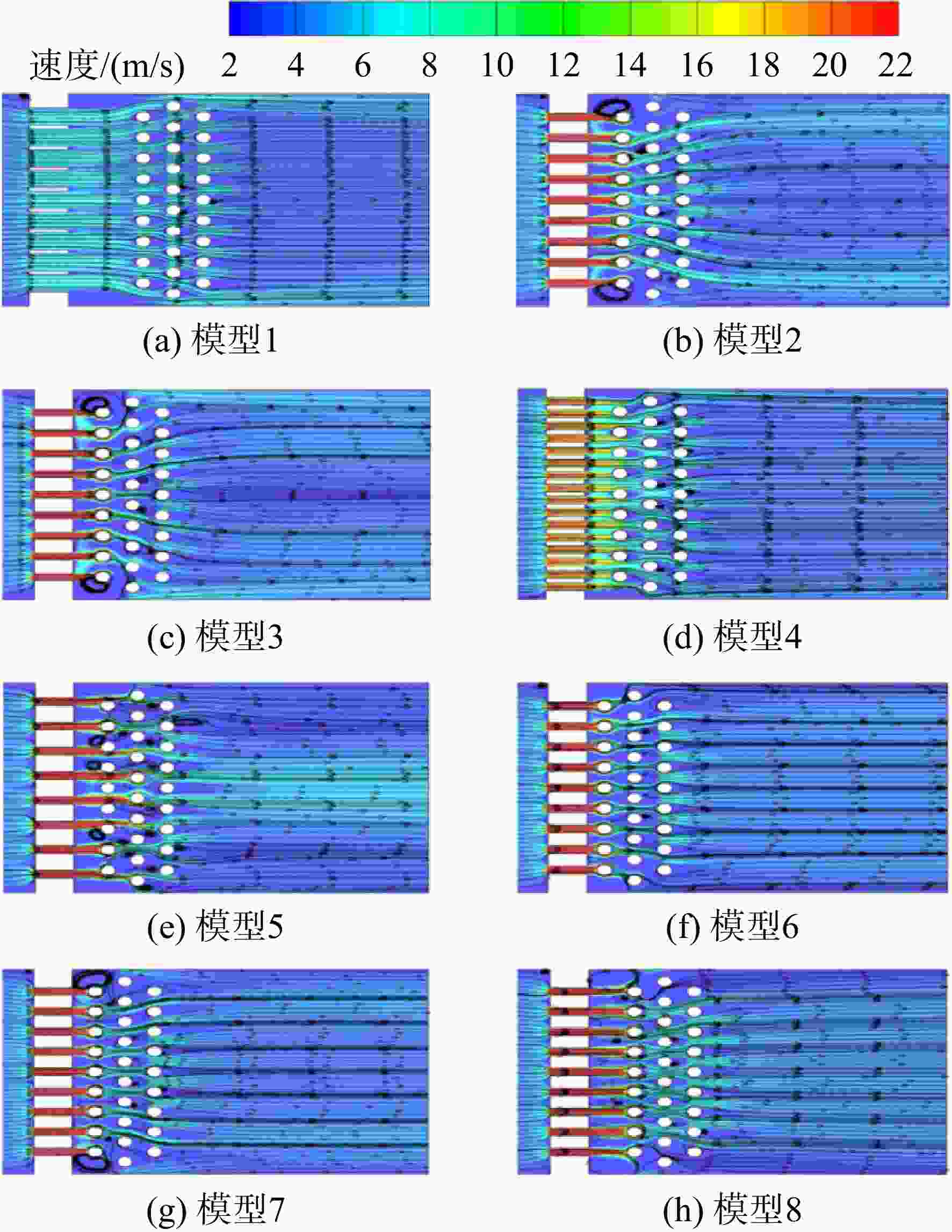
图 14 不同模型下XY平面中截面处流向速度和流线分布
Figure 14. Flow velocity and streamline distributions at middle cross-section of XY plane for different cases
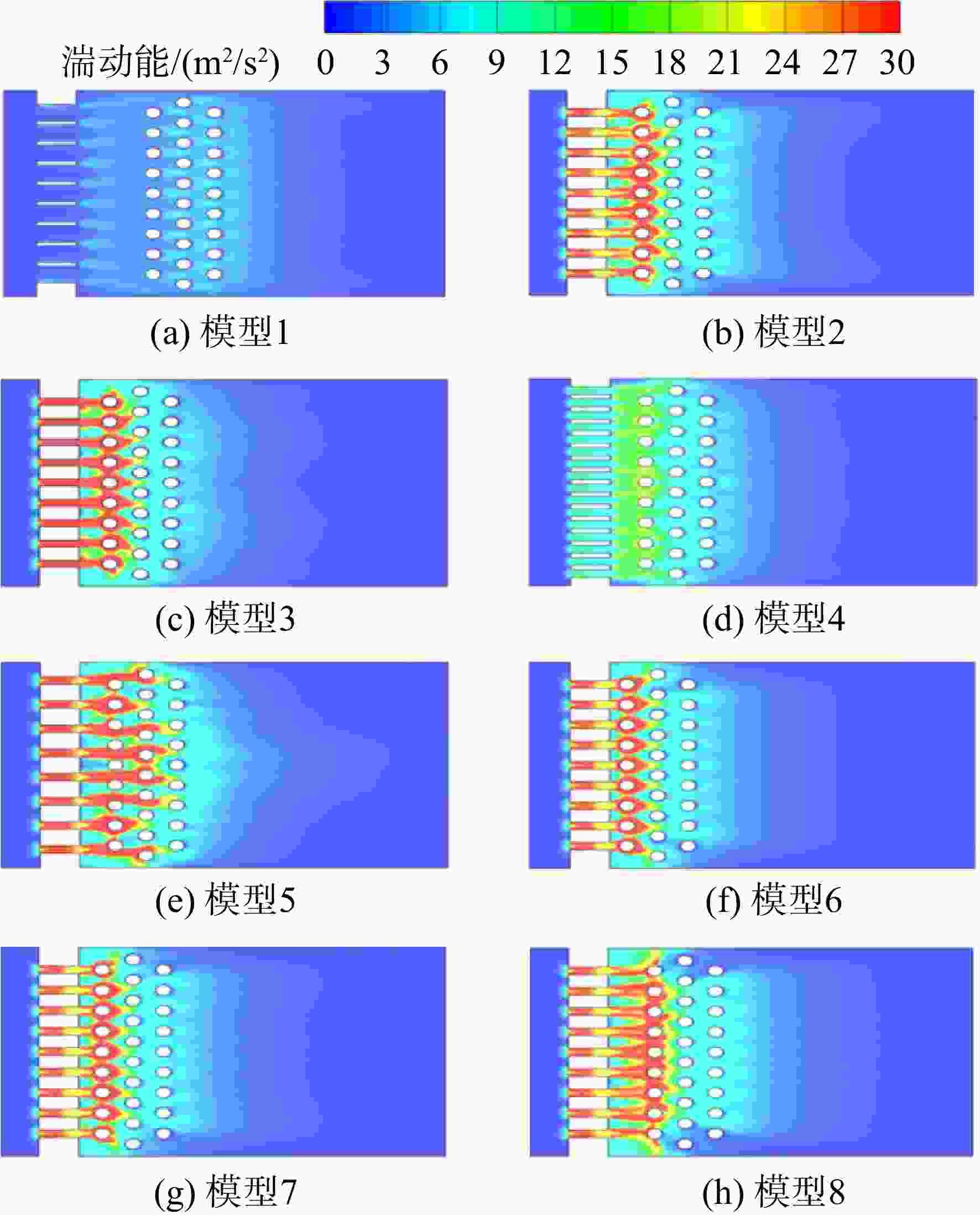
图 15 不同模型下XY平面湍动能分布
Figure 15. Distribution of turbulent energy in XY plane for different cases
表 1 冲击孔板的布置情况
Table 1. Layout of impingement perforated plate
编号 冲击孔径
dj/mm冲击孔径向
间距P/mm冲击距
H/dj穿孔率β 模型1 6.67 8 3 0.437 模型2 3.08 8 3 0.093 模型3 2.67 8 3 0.070 模型4 3.08 4.8 3 0.166 模型5 3.08 9.6 3 0.083 模型6 3.08 8 1.5 0.093 模型7 3.08 8 2 0.093 模型8 3.08 8 4 0.093  下载: 导出CSV
表 2 测量仪器和测量精度
Table 2. Measuring instruments and measuring accuracy
实验仪器和参数 测量仪器 精度 入口流量计 浮子流量计 2.5级 气流温度Tg 热电偶 ±0.5 K 壁面温度Tw 热色液晶、摄像机 ±0.5 K 实验件和气流初始温度T0 热电偶 ±0.5 K 实验时间t 摄像机 ±0.04 s 流量计压力ps 压力变送器 ±0.75% 实验压力p 差压计 ±0.1% 大气压力pa 大气压力表 ±0.1%
下载: 导出CSV
表 3 网格无关性验证
Table 3. Grid independence verification
参数 方案 网格1 网格2 网格3 网格4 网格数/万 220 400 600 1000 面积平均
表面传热系数/
(W/(m2·K))36.87 40.82 41.76 41.92 变化率/% 12.05 2.62 0.38
下载: 导出CSV
-
[1] HAN J C,DUTTA S,EKKAD S. Gas turbine heat transfer and cooling technology[M]. Boca Raton,US: CRC Press,2012. [2] HUANG Liang,LI Qingling,ZHAI Hongyan. Experimental study of heat transfer performance of a tube with different shaped pin fins[J]. Applied Thermal Engineering,2018,129: 1325-1332. doi: 10.1016/j.applthermaleng.2017.10.014 [3] XU J,YAO J X,SU P F,et al. Heat transfer and pressure loss characteristics of pin-fins with different shapes in a wide channel[R]. ASME GT2017-63761,2017. [4] FERSTER K K,KIRSCH K L,THOLE K A. Effects of geometry,spacing,and number of pin fins in additively manufactured microchannel pin fin arrays[J]. Journal of Turbomachinery,2018,140(1): 011007. doi: 10.1115/1.4038179 [5] SHEN Beibei,LI Yang,YAN Hongbin,et al. Heat transfer enhancement of wedge-shaped channels by replacing pin fins with Kagome lattice structures[J]. International Journal of Heat and Mass Transfer,2019,141: 88-101. doi: 10.1016/j.ijheatmasstransfer.2019.06.059 [6] JADHAV R S,BALAJI C. Fluid flow and heat transfer characteristics of a vertical channel with detached pin-fin arrays arranged in staggered manner on two opposite endwalls[J]. International Journal of Thermal Sciences,2016,105: 57-74. doi: 10.1016/j.ijthermalsci.2016.02.017 [7] AXTMANN M,POSER R,VON WOLFERSDORF J,et al. Endwall heat transfer and pressure loss measurements in staggered arrays of adiabatic pin fins[J]. Applied Thermal Engineering,2016,103: 1048-1056. doi: 10.1016/j.applthermaleng.2016.04.066 [8] 张丽,张书华,朱惠人,等. 小间距梯形扰流柱通道内的流动换热数值计算[J]. 航空动力学报,2009,24(1): 13-17. ZHANG Li,ZHANG Shuhua,ZHU Huiren,et al. Numerical simulation on flow and heat transfer in channel with small spacing short pin-fin arrays[J]. Journal of Aerospace Power,2009,24(1): 13-17. (in ChineseZHANG Li, ZHANG Shuhua, ZHU Huiren, et al. Numerical simulation on flow and heat transfer in channel with small spacing short pin-fin arrays[J]. Journal of Aerospace Power, 2009, 24(1): 13-17. (in Chinese) [9] LAWSON S A,THRIFT A A,THOLE K A,et al. Heat transfer from multiple row arrays of low aspect ratio pin fins[J]. International Journal of Heat and Mass Transfer,2011,54(17/18): 4099-4109. [10] CHYU M K,SIW S C,MOON H K. Effects of height-to-diameter ratio of pin element on heat transfer from staggered pin-fin arrays[R]. ASME GT2009-59814,2009. [11] LYALL M E,THRIFT A A,THOLE K A,et al. Heat transfer from low aspect ratio pin fins[J]. Journal of Turbomachinery,2011,133(1): 011001. doi: 10.1115/1.2812951 [12] PARK J S,KIM K M,LEE D H,et al. Heat transfer on rotating channel with various heights of pin-fin[R]. ASME GT2008-50783,2008. [13] KIRSCH K L,THOLE K A. Pressure loss and heat transfer performance for additively and conventionally manufactured pin fin arrays[J]. International Journal of Heat and Mass Transfer,2017,108: 2502-2513. doi: 10.1016/j.ijheatmasstransfer.2017.01.095 [14] LAU S C,CERVANTES J,HAN J C,et al. Internal cooling near trailing edge of a gas turbine airfoil with cooling airflow through blockages with holes[J]. Journal of Turbomachinery,2008,130(3): 031004. doi: 10.1115/1.2775489 [15] METZGER D E,FAN C S. Heat transfer in pin-fin arrays with jet supply and large alternating wall roughness ribs[J]. Fundamental and Applied Heat Transfer Research for Gas Turbine Engines,1992,226: 23-30. [16] XU Yang,ZHU Huiren,XU Weijiang,et al. Effect of pin fin arrangement on the heat transfer characteristics in a convergent channel with impingement[J]. International Journal of Heat and Mass Transfer,2018,125: 629-639. doi: 10.1016/j.ijheatmasstransfer.2018.04.111 [17] KAN R,REN J,JIANG H D. Combined effects of perforated blockages and pin fins in a trailing edge internal cooling duct[R]. ASME GT 2014-25767,2014. [18] SCHEKMAN S,KIM T. Orifice jet curvature and its interaction with a row of short pin-fins[J]. Journal of Fluids Engineering,2024,146(5): 051302. doi: 10.1115/1.4064008 [19] KONG Dehai,GUO Tao,MA Zhao,et al. Investigation of impingement heat transfer in double-wall cooling structures with corrugated impingement plate at small Reynolds numbers[J]. Applied Thermal Engineering,2023,225: 120204. doi: 10.1016/j.applthermaleng.2023.120204 [20] HOLMAN J P. Heat transfer[M]. Sixth ed. New York,US: McGrew Hill Book Company,1989. [21] PETUKHOV,B S. Turbulent pipe flow with variable physical properties[J]. Advances in Heat Transfer,1970,6: 503-564. [22] MOFFAT R J. Describing the uncertainties in experimental results[J]. Experimental Thermal Fluid Science,1988,1: 3-17. doi: 10.1016/0894-1777(88)90043-X -


 点击查看大图

计量
- 文章访问数: 457
- HTML浏览量: 326
- PDF量: 74
- 被引次数: 0