






Perforated Gurney flaps to improve hovering performance of helicopter rotors
-
摘要:
对布孔格尼襟翼提升直升机旋翼悬停性能进行了研究,首先采用计算流体动力学(CFD)方法对布孔格尼襟翼的气动特性进行了探讨,建立了加装布孔格尼襟翼的翼型气动模型,在此基础上,将该模型与直升机飞行性能分析模型相耦合,分析了直升机旋翼加装布孔格尼襟翼后的性能提升。结果表明:布孔格尼襟翼上的孔洞射流作用打断了尾缘脱落涡,从而降低了阻力、提升了升阻比。悬停性能分析结果表明:桨叶加装格尼襟翼后,以略微牺牲轻载时性能为代价,能有效提升大载荷时悬停效率并降低需用功率,降低旋翼桨叶迎角,改善桨叶承载分布,且布孔格尼襟翼对性能的提升效果随安装位置向外扩展而增加明显。2%弦长高度、23%孔隙度、加装在桨叶展向80%~95%半径位置的布孔格尼襟翼,在大载荷时可将悬停效率提升10.60%,功率消耗减小10.00%。将旋翼最大拉力提升5.17%,对应悬停效率提升7.82%。
Abstract:A study was conducted for the improvement of hovering performance by perforated gurney flaps’ application on helicopter rotor. First, the aerodynamic characteristics of perforated gurney flaps were discussed using computational fluid dynamics (CFD) method, and then an aerodynamic model of flapped airfoil was established. The performance improvement of the helicopter rotor equipped with perforated gurney flaps was analyzed by the coupling of a helicopter flight performance analysis model with the perforated gurney flap aerodynamic model. The results indicated that the jets brought by the holes interruptted the trailing-edge vortex shedding, thereby reducing the drag and increasing the lift to drag ratio. The analysis of hovering performance showed that after the installation of gurney flaps, at the cost of slightly sacrificing performance under low loads, a significant increment of figure of merit and reduction of power required under high loads was achieved. Also a reduction of angle of attack of rotor blade was convinced, thus the blade load distribution was improved. The afore mentioned effects of perforated gurney flaps increased significantly with the outward expansion of installation position. A 2% chord height, 23% porosity perforated gurney flap equipped at the radial 80% to 95% radius of the rotor blade can increase figure of merit by 10.60% and reduce power required by 10.00% under high loads, thus the maximum thrust of the rotor increased by 5.17% and the corresponding figure of merit increased by 7.82%.
-
Key words:
- Gurney flap /
- helicopter /
- hover performance /
- perforated Gurney flap /
- power required /
- figure of merit
-
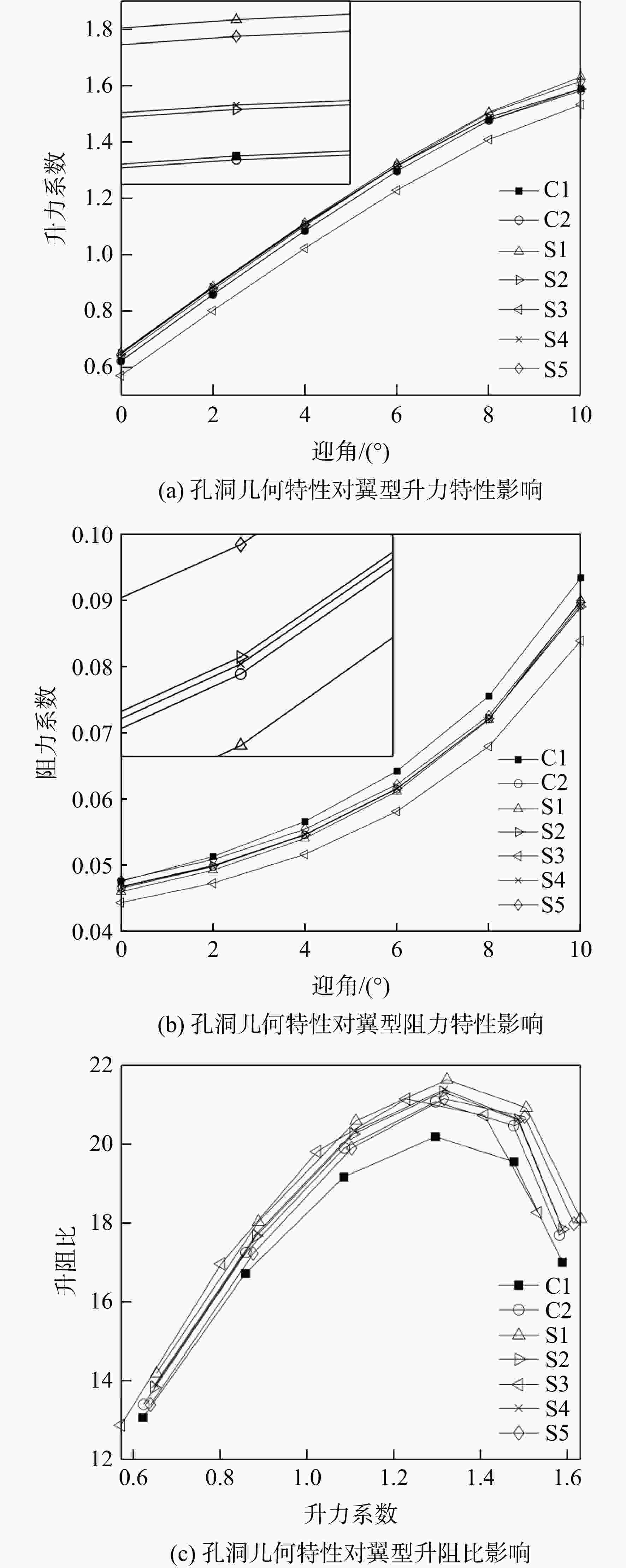
图 3 布孔方式对格尼襟翼气动特性影响
Figure 3. Holes’ geometry influence on aerodynamic characteristics of Gurney flap
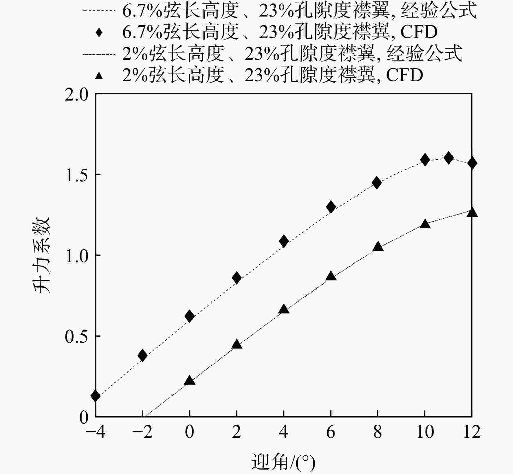
图 6 公式预测布孔格尼襟翼升力系数
Figure 6. Formula prediction of lift coefficient of perforated Gurney flap
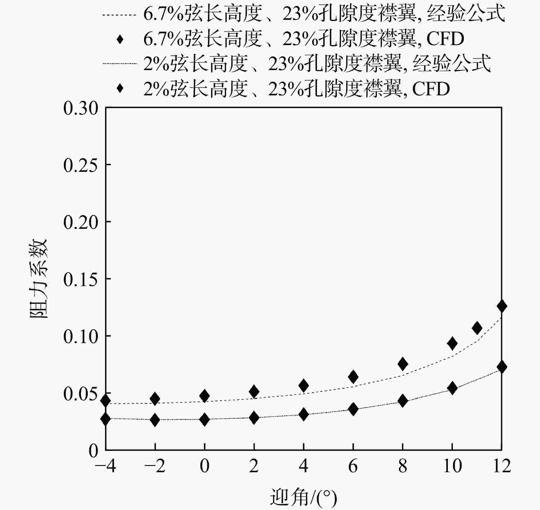
图 7 公式预测布孔格尼襟翼阻力系数
Figure 7. Formula prediction of drag coefficient of perforated Gurney flap
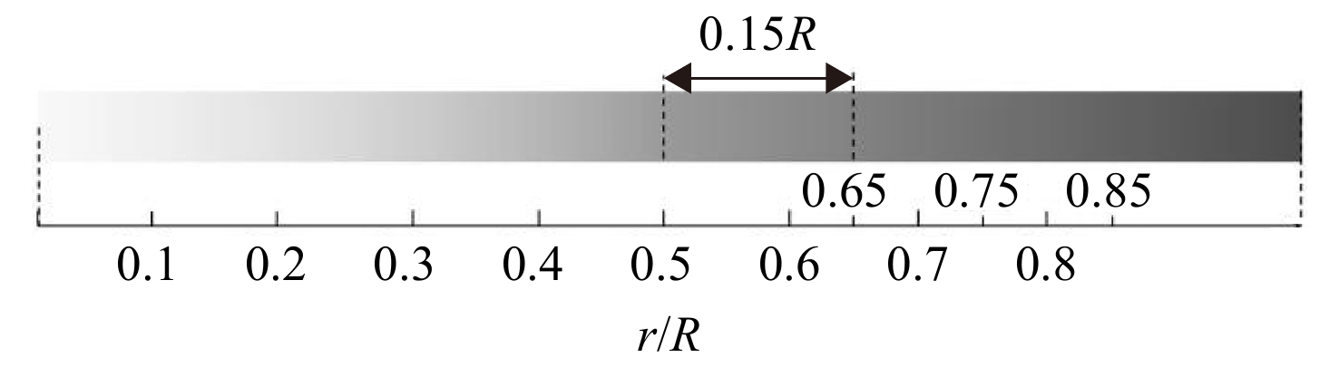
图 10 孔格尼襟翼于旋翼桨叶上加装方案
Figure 10. Perforated Gurney flap installation sets in rotor blades
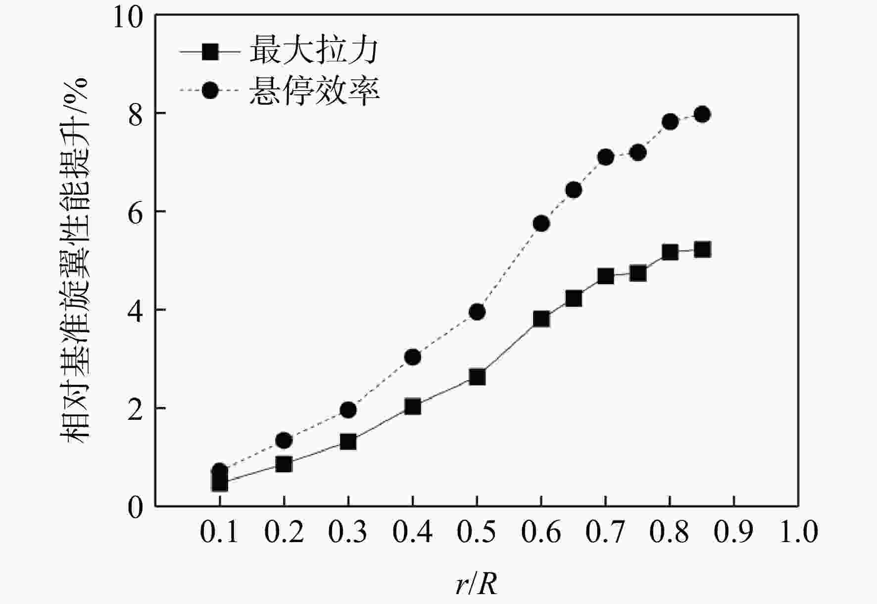
图 13 布孔格尼襟翼对旋翼最大拉力和悬停效率影响
Figure 13. Perforated Gurney flaps’ influence on the maximum thrust and figure of merit
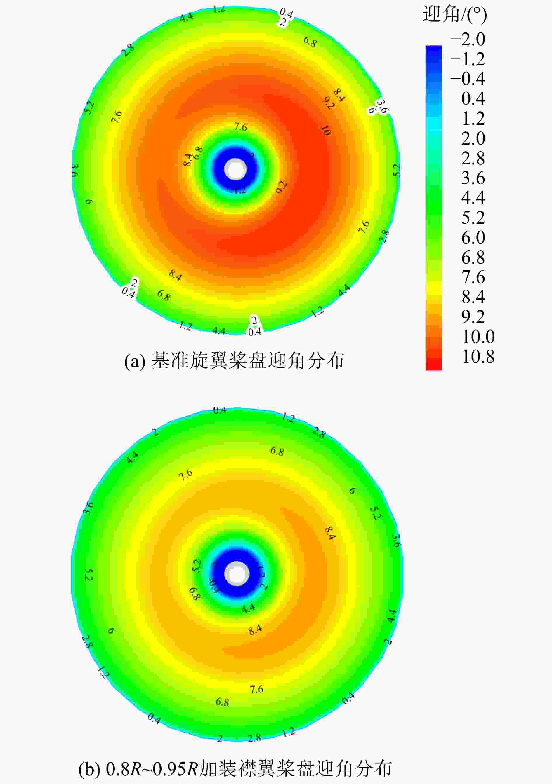
图 14 布孔格尼襟翼对旋翼桨盘迎角分布影响
Figure 14. Perforated Gurney flaps’ influence on angle of attack of rotor disc
表 1 CFD参数设置
Table 1. CFD settings
参数 数值 二维验证 三维验证 翼型弦长/m 1 0.15 格尼襟翼高度与翼型弦长之比/% 0,2,3 6.7 孔隙度/% 0,23 雷诺数/105 21 2.32 第1层网格高度/10−5m 2.4 2.5  下载: 导出CSV
表 2 布孔格尼襟翼孔洞几何参数设置
Table 2. Perforated Gurney flap geometry sets
编号 示意图 相关参数/mm R a b
C1
C2
0.8
1.08
1.8
2.5
2.4
3.2S1 
1.62 3.75 2.5 S2 1.62 3.75 5 S3 1.62 3.75 7.5 S4 1.45 3 5 S5 2.16 6.67 5
下载: 导出CSV
表 3 UH-60A直升机主要参数
Table 3. UH-60A helicopter main parameters
参数 数值及详情 旋翼 半径/m 8.178 翼型 SC 1095/SC 1094R8 桨叶片数 4 转速/(rad/s) 27.0 弦长/m 0.5273 挥舞铰偏置/m 0.3817 尾桨 半径/m 1.6764 翼型 SC 1095 桨叶片数 4 转速/(rad/s) 124.62 弦长/m 0.2469 负扭/(°) −18.0
下载: 导出CSV
-
[1] LIEBECK R H. Design of subsonic airfoils for high lift[J]. Journal of Aircraft, 1978, 15(9): 547-561. doi: 10.2514/3.58406 [2] NEUHART D, PENDERGRAFT O C. A water tunnel study of Gurney flaps[R]. Hampton, US: Langley Research Center, NASA-TM-4071, 1988. [3] JANG C S. Incompressible Navier-Stokes computations of an airfoil with a Gurney flap[D]. San Luis Obispo, US: California Polytechnic State University, 1992. [4] JEFFREY D R M. An investigation into the aerodynamics of Gurney flaps [D]. Southampton, US: University of Southampton, 1998. [5] KENTFIELD J. The potential of Gurney flaps for improving the aerodynamic performance of helicopter rotors[R]. AIAA-1993-4883, 1993. [6] GIBERTINI G, ZANOTTI A, DROANDI G, et al. Experimental investigation of a helicopter rotor with Gurney flaps[J]. The Aeronautical Journal, 2017, 121(1236): 191-212. doi: 10.1017/aer.2016.120 [7] DEHAEZE F, BAVERSTOCK K D, BARAKOS G N. CFD simulation of flapped rotors[J]. The Aeronautical Journal, 2015, 119(1222): 1561-1583. doi: 10.1017/S0001924000011404 [8] YEE K, JOO W, LEE D H. Aerodynamic performance analysis of a Gurney flap for rotorcraft application[J]. Journal of Aircraft, 2007, 44(3): 1003-1014. doi: 10.2514/1.26868 [9] 张勇刚, 崔钊, 韩东, 等. 加装格尼襟翼旋翼的直升机飞行性能[J]. 航空学报, 2016, 37(7): 2208-2217. ZHANG Yonggang, CUI Zhao, HAN Dong, et al. Flight performance of helicopter rotors with Gurney flaps[J]. Acta Aeronautica et Astronautica Sinica, 2016, 37(7): 2208-2217. (in ChineseZHANG Yonggang, CUI Zhao, HAN Dong, et al. Flight performance of helicopter rotors with Gurney flaps[J]. Acta Aeronautica et Astronautica Sinica, 2016, 37(7): 2208-2217. (in Chinese) [10] STACEY S, CONNOLLY N, COURT P. Leonardo helicopter active rotor programmes to improve helicopter comfort & performance[R]. Phoenix, US: 74th American Helicopter Society International Annual Forum and Technology Display, 2018. [11] KO L S. An experimental investigation of airfoils with perforated Gurney-type flaps[D]. Montréal, Canada: McGill University, 2011. [12] LEE T. Aerodynamic characteristics of airfoil with perforated Gurney-type flaps[J]. Journal of Aircraft, 2009, 46(2): 542-548. doi: 10.2514/1.38474 [13] PURSER P E, TURNER T R. Aerodynamic characteristics and flap loads of perforated double split flaps on a rectangular NACA 23012 airfoil[R]. Washington, US: Langley Memorial Aeronautical Laboratory, NACA-WR-L-415, 1943. [14] MEYER R, HAGE W, BECHERT D W, et al. Drag reduction on Gurney flaps by three-dimensional modifications[J]. Journal of Aircraft, 2006, 43(1): 132-140. doi: 10.2514/1.14294 [15] TRAUB L W, MILLER A C, REDINIOTIS O. Preliminary parametric study of Gurney flap dependencies[J]. Journal of Aircraft, 2006, 43(4): 1242-1244. doi: 10.2514/1.13852 [16] KAMNIS S, KONTIS K. Numerical studies on the application of synthetic jets for the active control of subsonic flow configurations[R]. AIAA-2004-2609, 2004. [17] LI Yachen, WANG Jinjun, ZHANG Panfeng. Effects of Gurney flaps on a NACA0012 airfoil[J]. Flow, Turbulence and Combustion, 2002, 68(1): 27-39. doi: 10.1023/A:1015679408150 [18] BACH A B, PECHLIVANOGLOU G, NAYERI C, et al. Wake vortex field of an airfoil equipped with an active finite Gurney flap[R]. AIAA-2015-1271, 2015. [19] LIU Tianshu, MONTEFORT J. Thin-airfoil theoretical interpretation for Gurney flap lift enhancement[J]. Journal of Aircraft, 2007, 44(2): 667-671. doi: 10.2514/1.27680 [20] HAN Dong, DONG Chen, BARAKOS G N. Performance improvement of variable speed rotors by Gurney flaps[J]. Aerospace Science and Technology, 2018, 81: 118-127. doi: 10.1016/j.ast.2018.07.044 [21] 高正, 陈仁良. 直升机飞行动力学[M]. 北京: 科学出版社, 2003: 65-75. [22] HILBERT K B. A mathematical model of the UH-60 helicopter[R]. Moffett Field, US: AMSE Research Center, NASA-TM-85890, 1984. [23] YEO H, BOUSMAN W G, JOHNSON W. Performance analysis of a utility helicopter with standard and advanced rotors[J]. Journal of the American Helicopter Society, 2004, 49(3): 250-270. doi: 10.4050/JAHS.49.250 [24] NAGATA J, PIOTROWSKI J L, YOUNG C J. Basline performance verification of the 12th year production UH-60A black hawk helicopter[R]. Washington, US: United States Department of the Army, ADA208671, 1989. -


 点击查看大图

计量
- 文章访问数: 554
- HTML浏览量: 396
- PDF量: 27
- 被引次数: 0