






A numerical study of the tapered-land cutback cooling structure effects on shock and wake losses of transonic turbine blade
-
摘要:
激波和尾迹损失是高负荷跨声速气冷涡轮动叶气动损失的主要来源。压力面侧半劈缝冷却能够在降低热负荷的同时调控气动损失,但半劈缝结构特征与损失的关联尚未得到阐明。构建了末端呈锥形的筋板结构,并采用稳态数值计算方法,探究锥形筋板半劈缝结构对跨声速涡轮动叶激波和尾迹损失的影响机理。结果表明:对于激波损失,锥形筋板结构通过流道提前扩张使主流提前加速并折转,而在内伸激波波前的膨胀程度减弱,使波前马赫数及激波角减小,内伸激波及反射波损失下降。对于尾迹损失,锥形筋板结构通过提高尾缘后基压、改善速度分布的均匀性,有效削弱主流与冷气的动量输运过程,使尾迹沿流向更迅速弱化,尾迹损失下降。锥形筋板相比原型半劈缝结构在提高尾缘气膜冷却效率的同时,使较宽的落压比(不低于2.70)及冷气量(0%~3%)变化范围内的能量损失系数均得到降低。
Abstract:Shock and wake losses are the main sources of aerodynamic losses of a highly-loaded transonic air-cooled turbine blade. Pressure-side cutback cooling can control aerodynamic losses while reducing trailing-edge thermal load, but the relationship between the structural features and the losses remains unclear. In this study, a land structure with a tapered end was constructed, and steady-state numerical calculations were performed to investigate the effect of the tapered-land cutback structure on the shock and wake losses in a transonic turbine blade. The results showed that, for the shock loss, the tapered-land cutback structure induced an earlier flow acceleration and deflection via upstream flow area expansion, thereby mitigating the pre-shock expansion on the pressure side. Therefore, the Mach number and the shock angle were reduced and the losses of the pressure-side shock wave and the reflected shock wave decreased. For the wake loss, the tapered-land cutback structure effectively weakened the momentum transport between the mainstream and the coolant by increasing the base pressure downstream of the trailing edge and improving the uniformity of the velocity distribution. As a result, the wake was attenuated more rapidly along the flow direction and the wake loss decreased. The tapered-land cutback structure effectively reduced the energy loss coefficient over a wide range of the pressure ratio (exceeding 2.70) and the coolant flow rate (0%—3%) while also improving the trailing edge film cooling effectiveness.
-
Key words:
- transonic turbine /
- trailing edge cutback cooling /
- tapered land /
- shock loss /
- wake loss
-
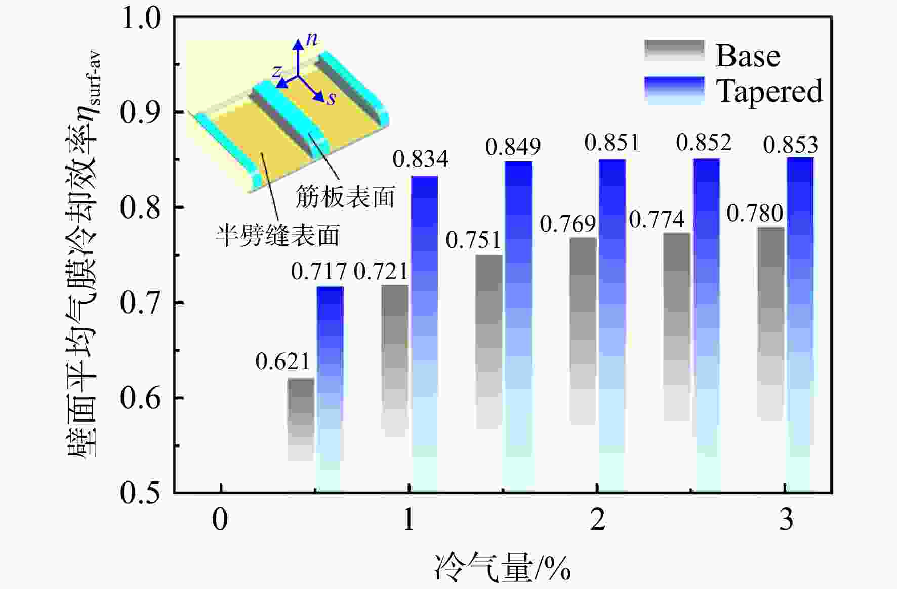
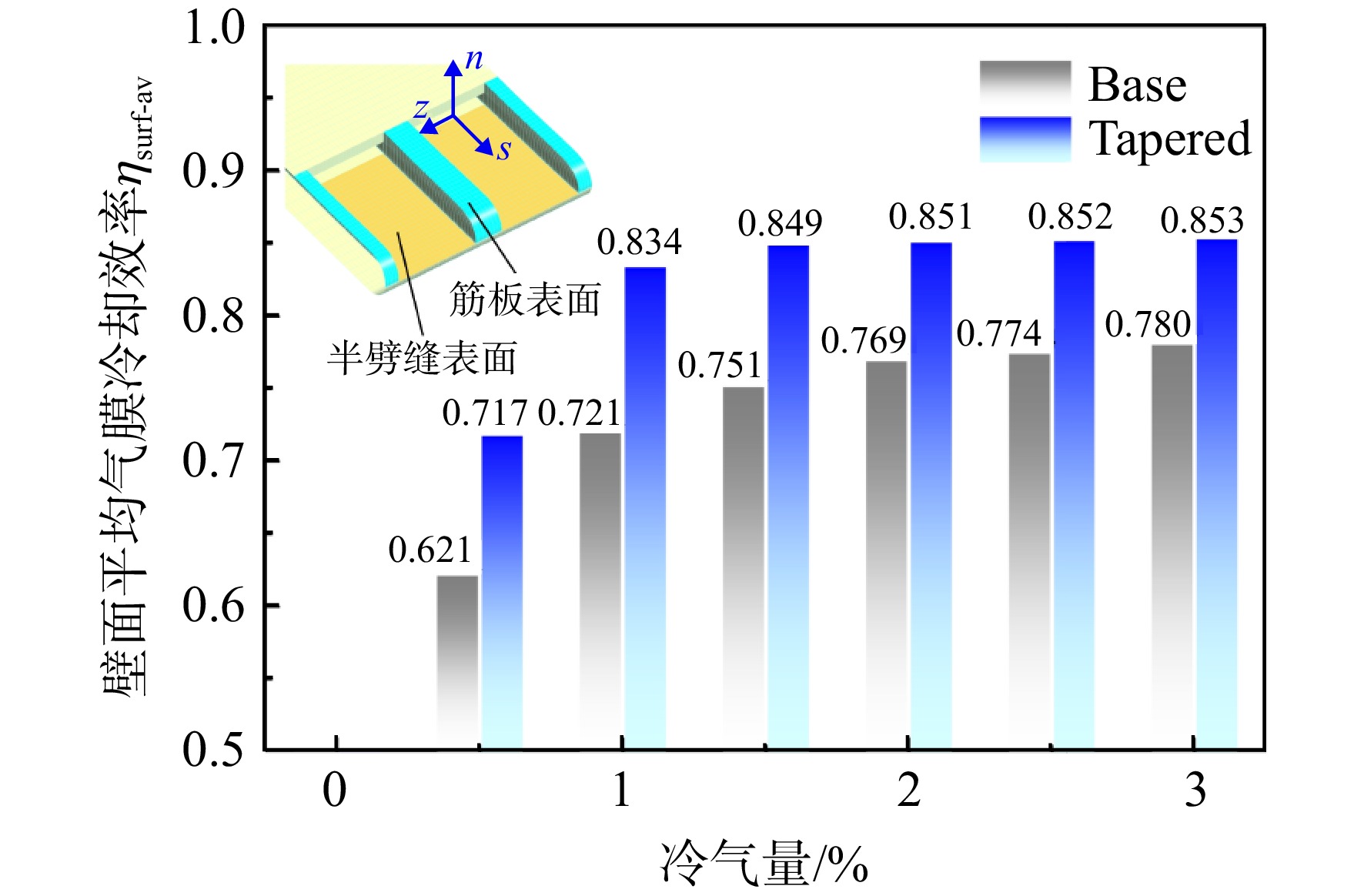
图 7 不同冷气量下的尾缘区域壁面平均气膜冷却效率η
Figure 7. Surface-averaged film cooling effectiveness η of trailing edge region under different coolant ratios
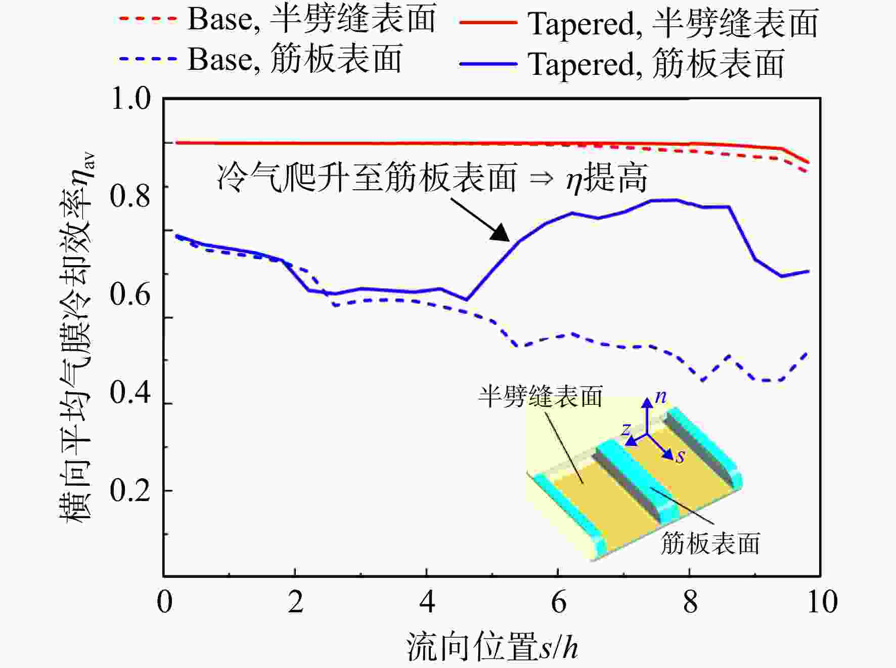
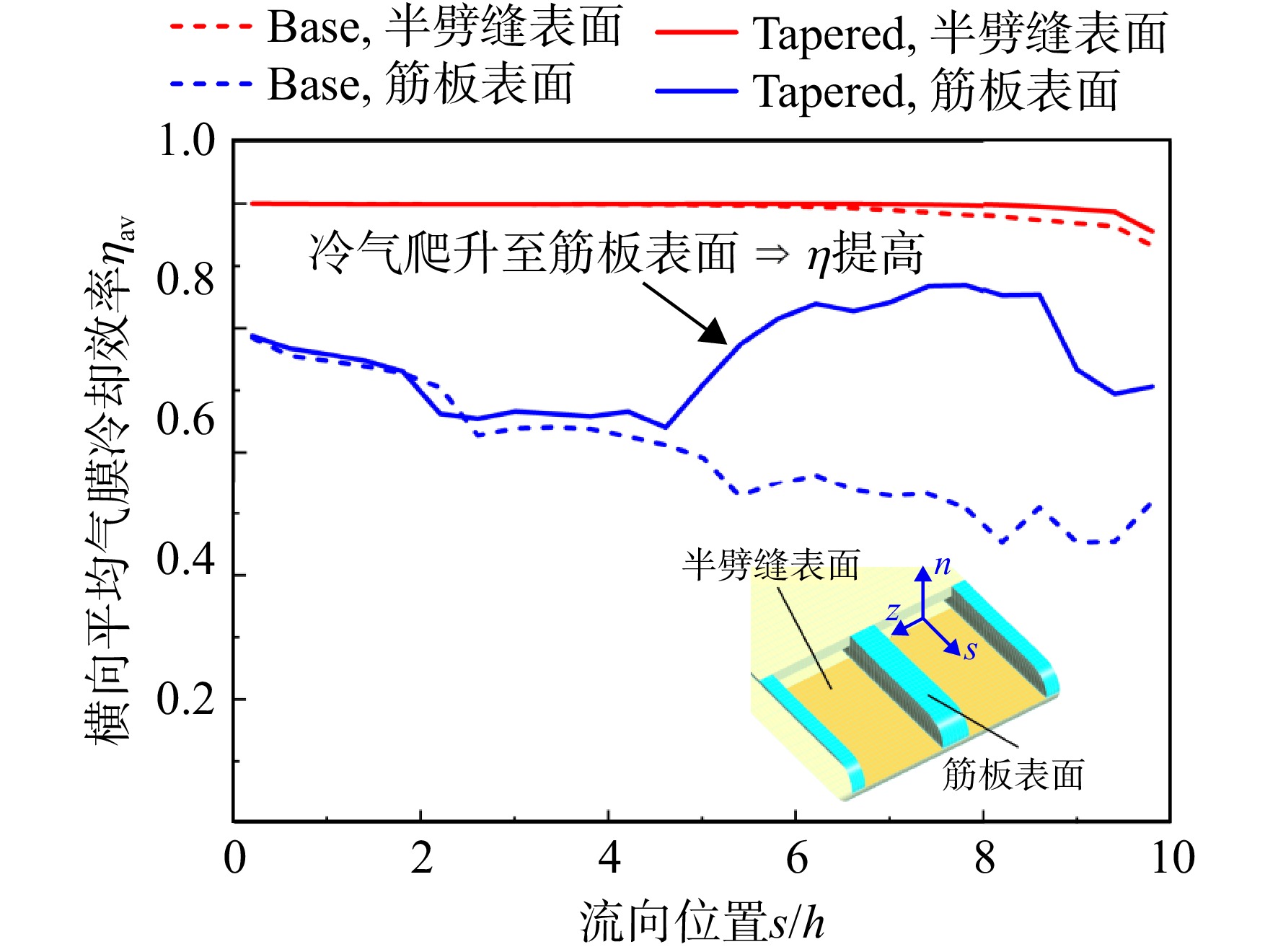
图 8 1%冷气量时劈缝和筋板表面的横向平均气膜冷却效率η沿流向s的变化曲线
Figure 8. Curves of spanwise-averaged film cooling effectiveness η of cutback and land surfaces changing with flow-direction coordinate s under 1% coolant ratio
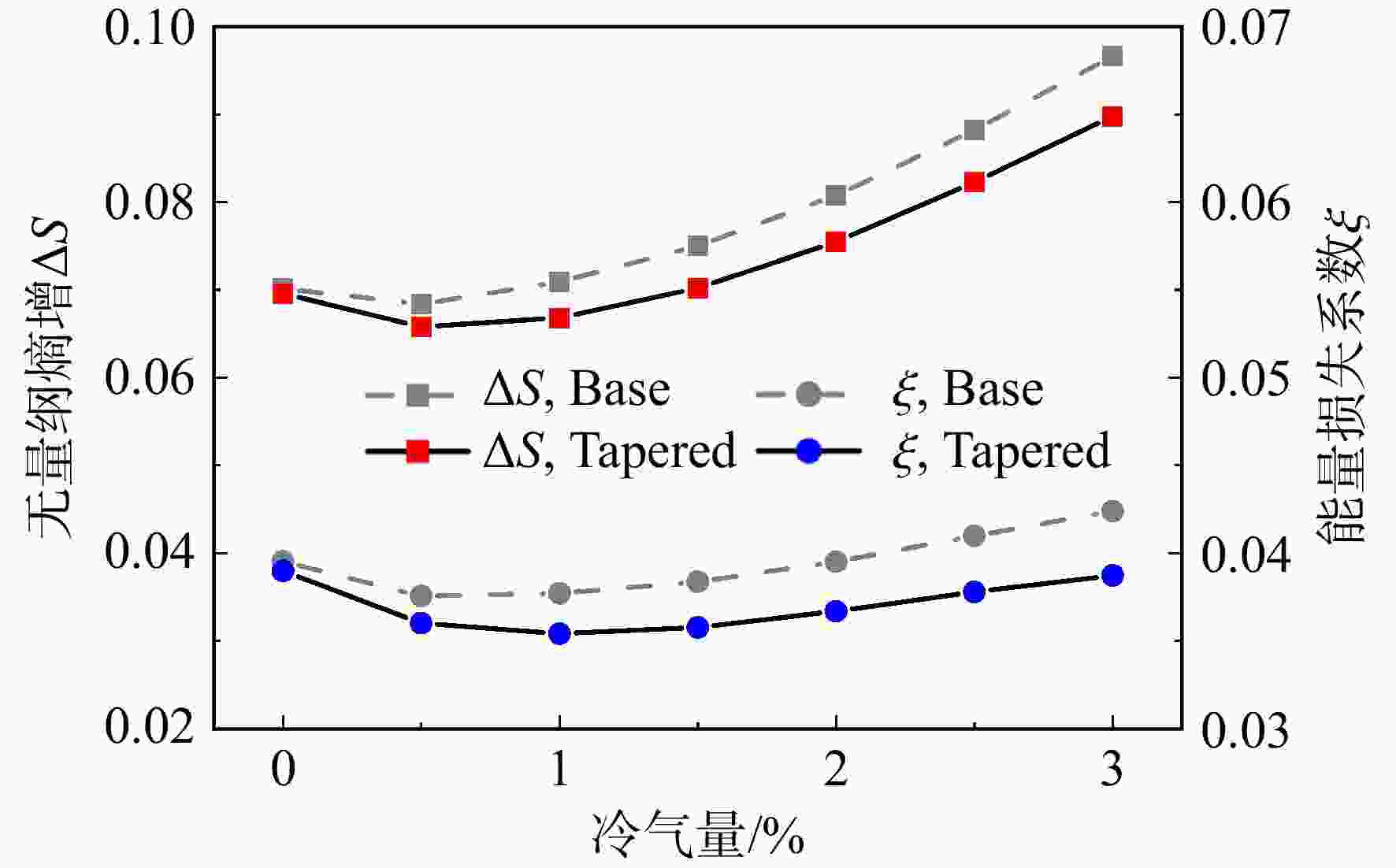
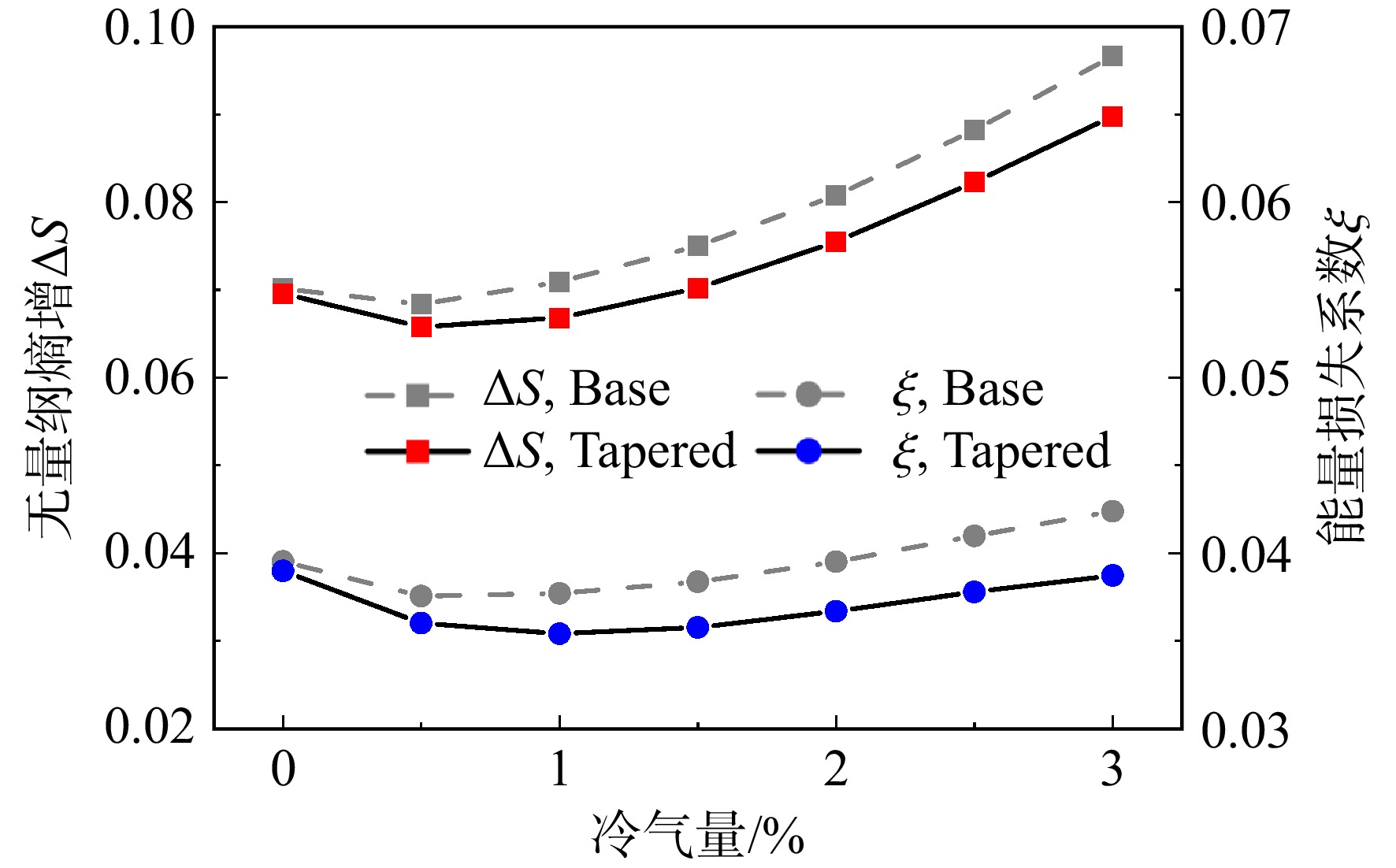
图 9 无量纲熵增ΔS0-2和能量损失系数ξ随冷气量变化曲线
Figure 9. Curves of dimensionless entropy rise ΔS0-2 and energy loss coefficient ξ changing with coolant ratio
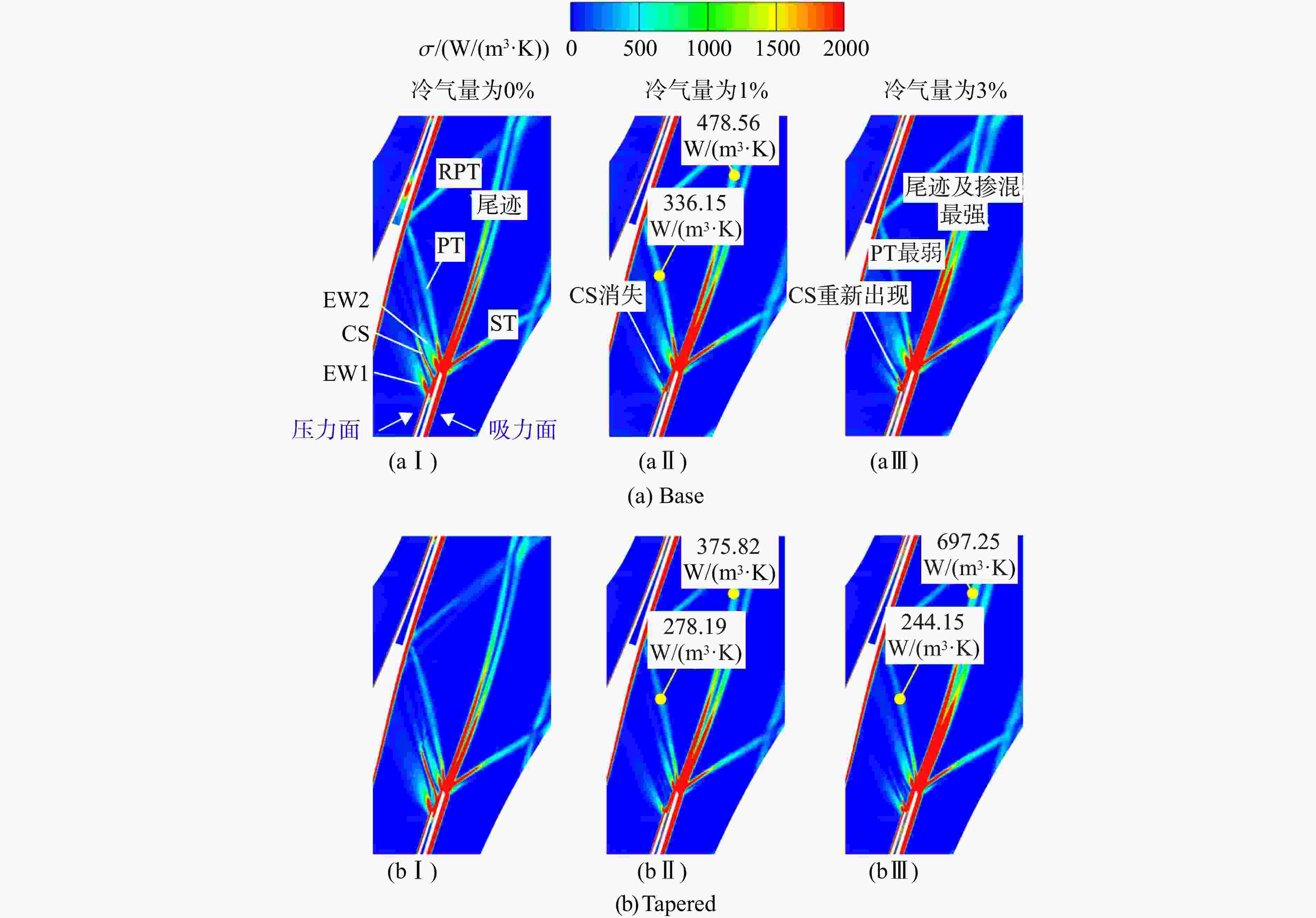
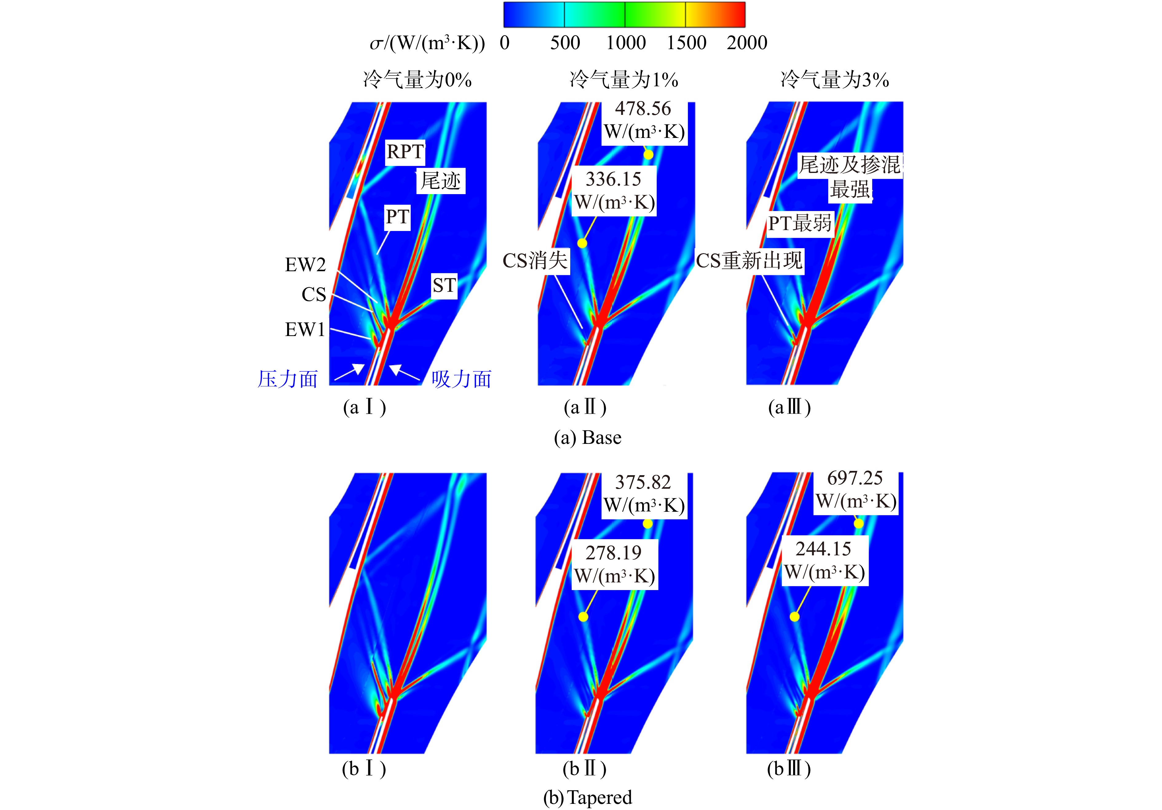
图 10 0%、1%及3%冷气量下B2B截面熵产率σ云图
Figure 10. Contours of entropy generation rate σ at B2B cross-section under 0%, 1% and 3% coolant ratios
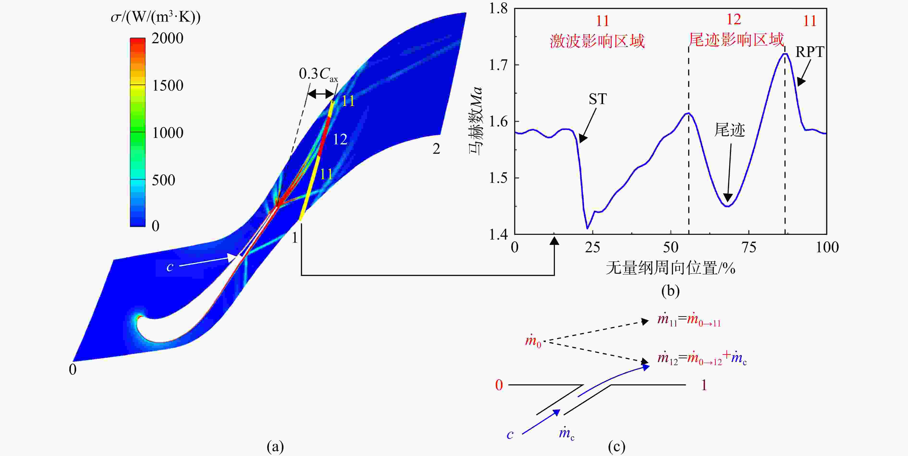
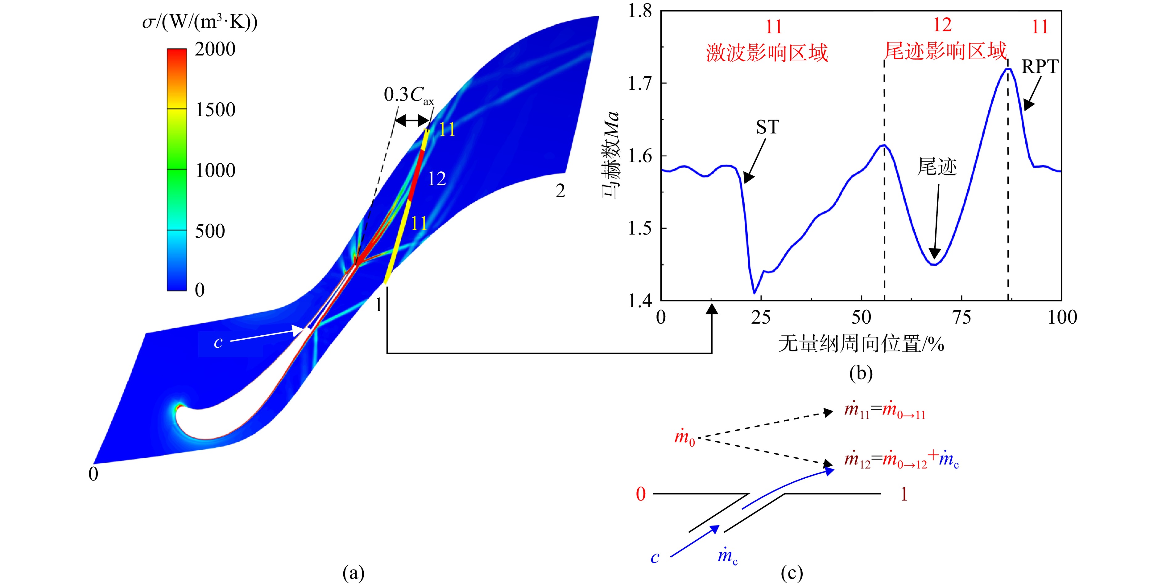
图 11 尾缘冷气注入时的激波与尾迹损失量化计算方法
Figure 11. Quantitative method of shock loss and wake loss with trailing edge coolant injection
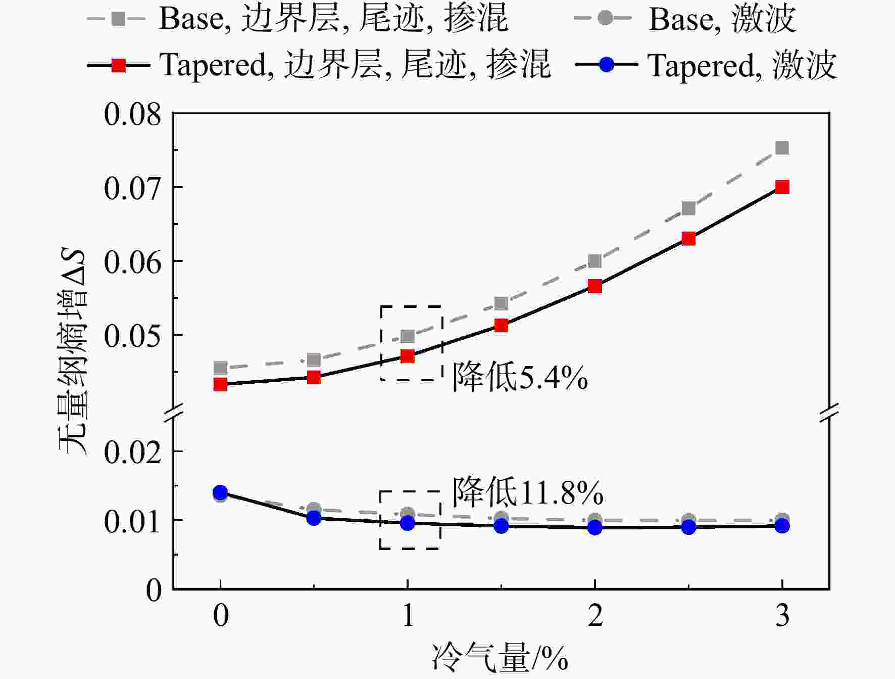
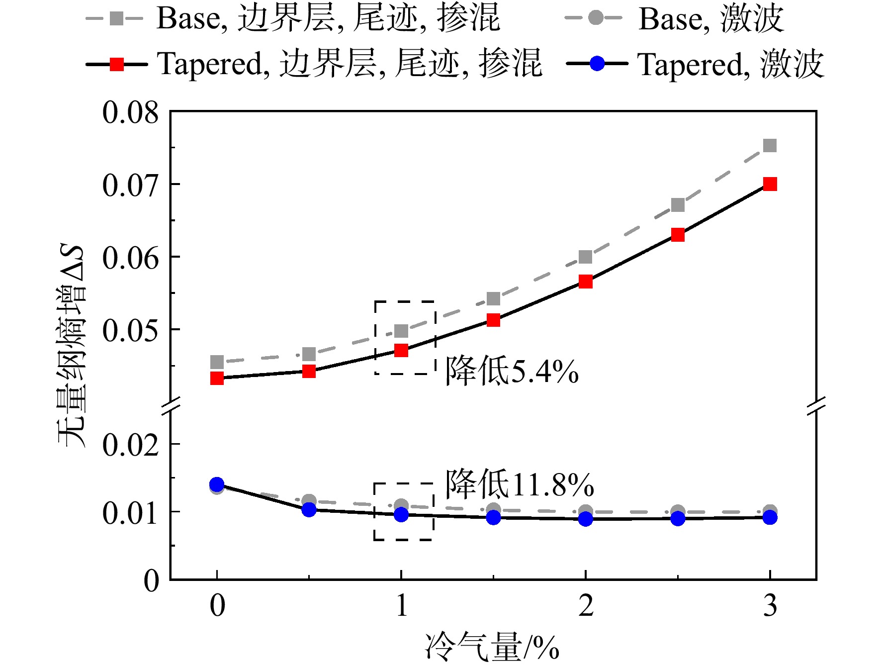
图 12 激波和尾迹引起的无量纲熵增ΔS0-1随冷气量变化曲线
Figure 12. Curves of dimensionless entropy rise ΔS0-1 caused by shock and wake changing with coolant ratio
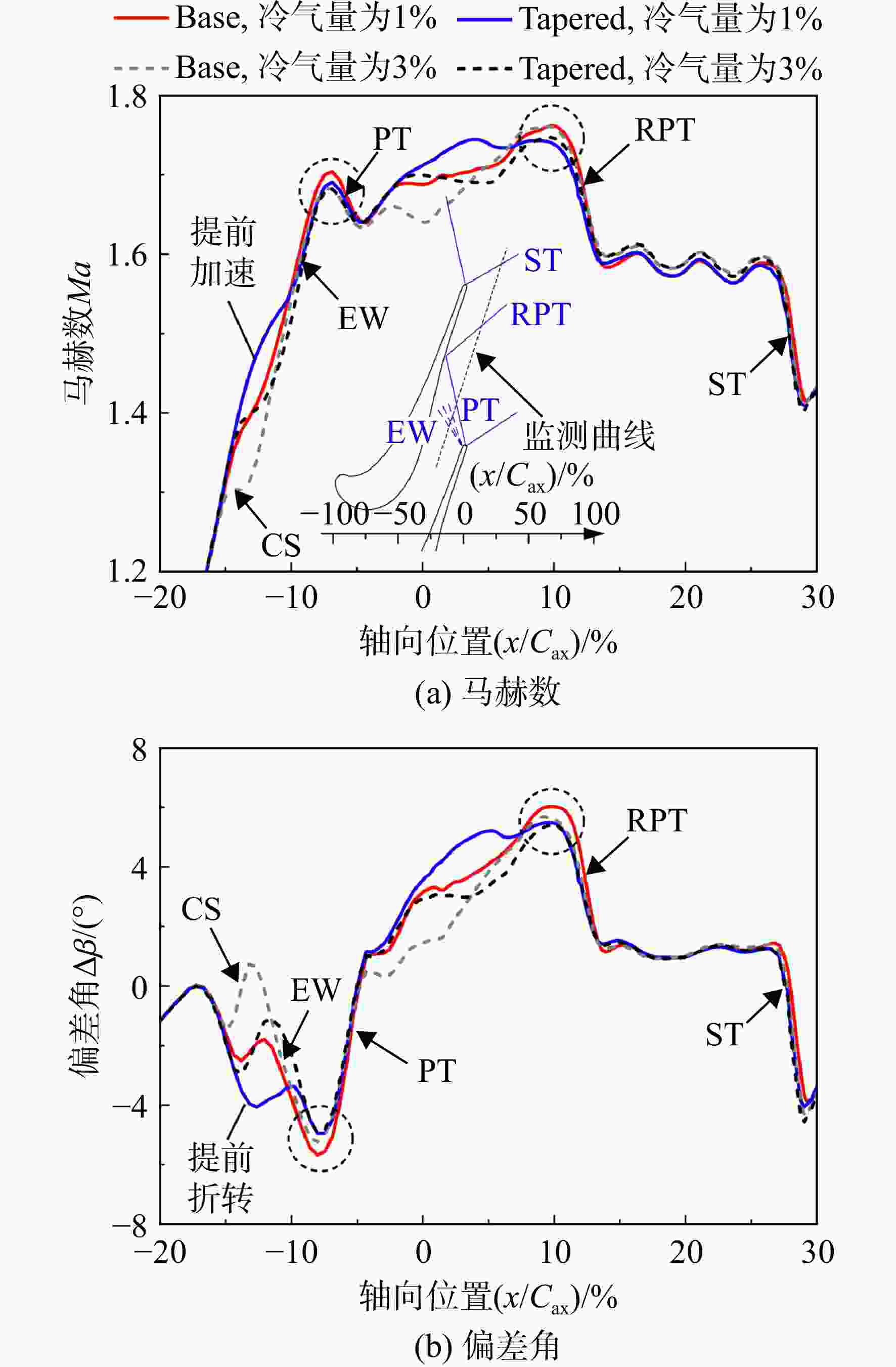
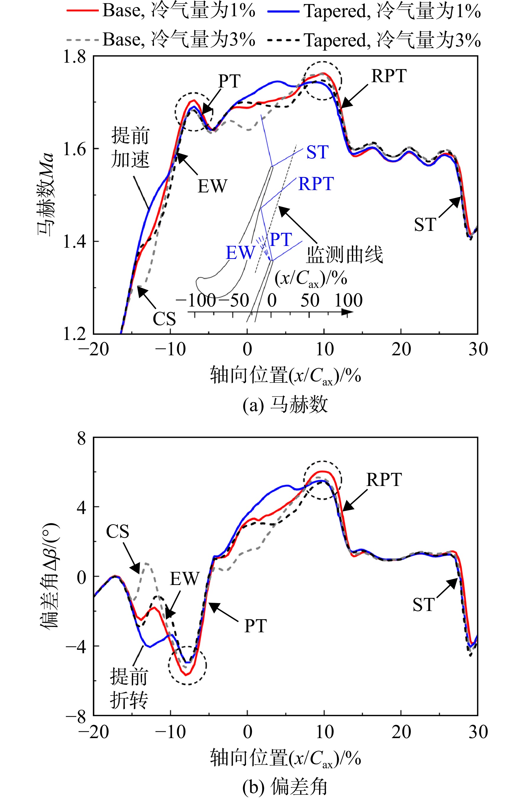
图 13 1%及3%冷气量时马赫数Ma和偏差角Δβ沿轴向位置x变化曲线
Figure 13. Curves of Mach number Ma and deviation angle Δβ change along axial location x under1% and 3% coolant ratios
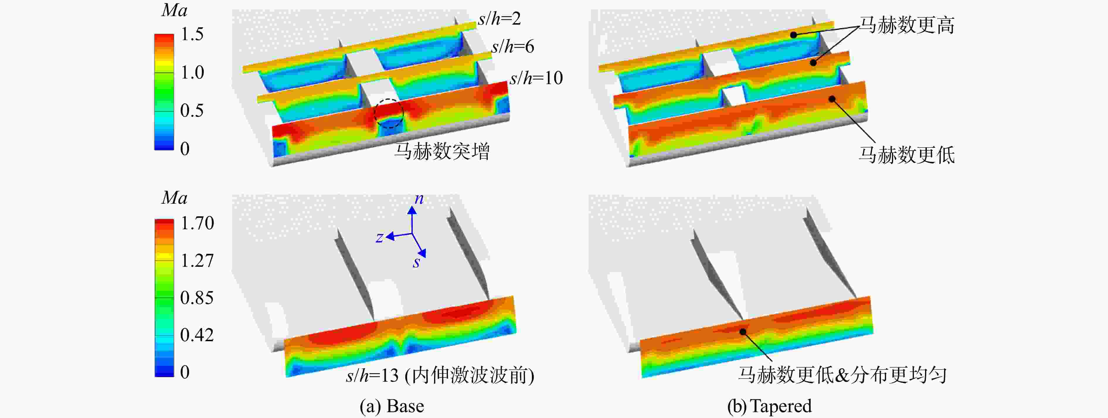
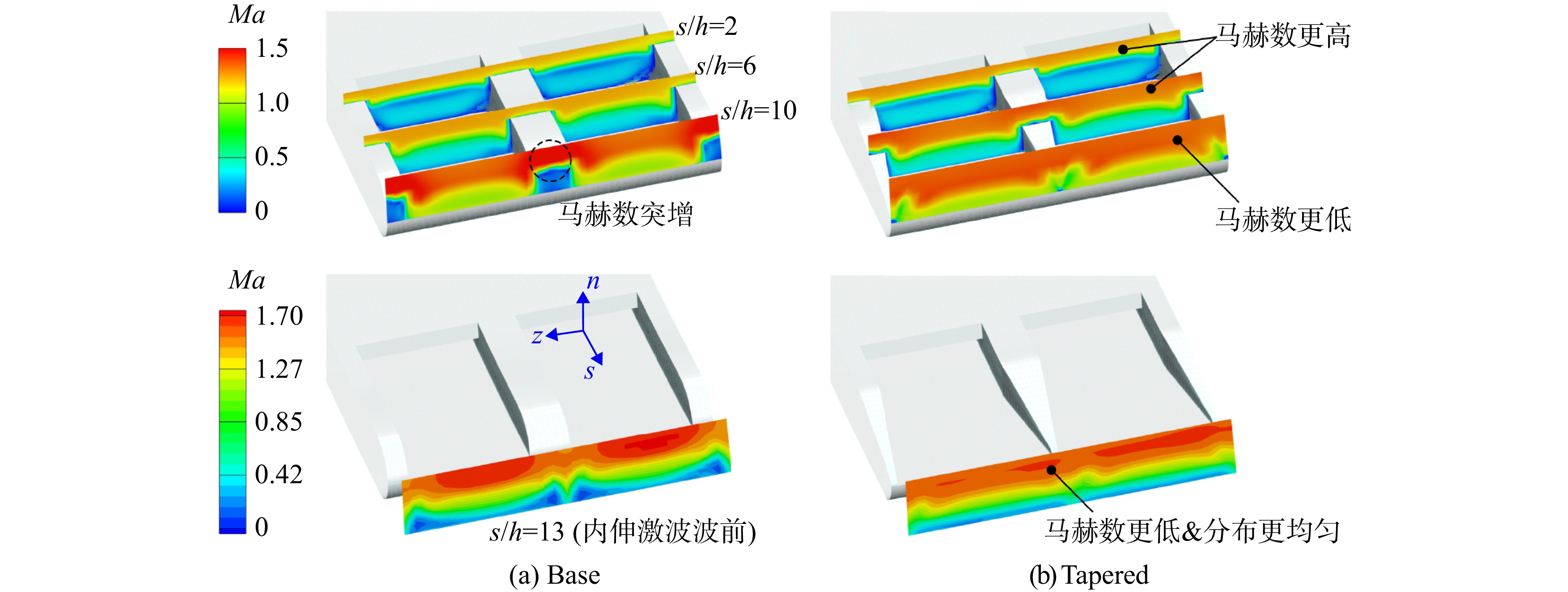
图 14 1%冷气量时不同流向位置s处的Ma云图
Figure 14. Contours of Ma at different flow-direction coordinate s under 1% coolant ratio
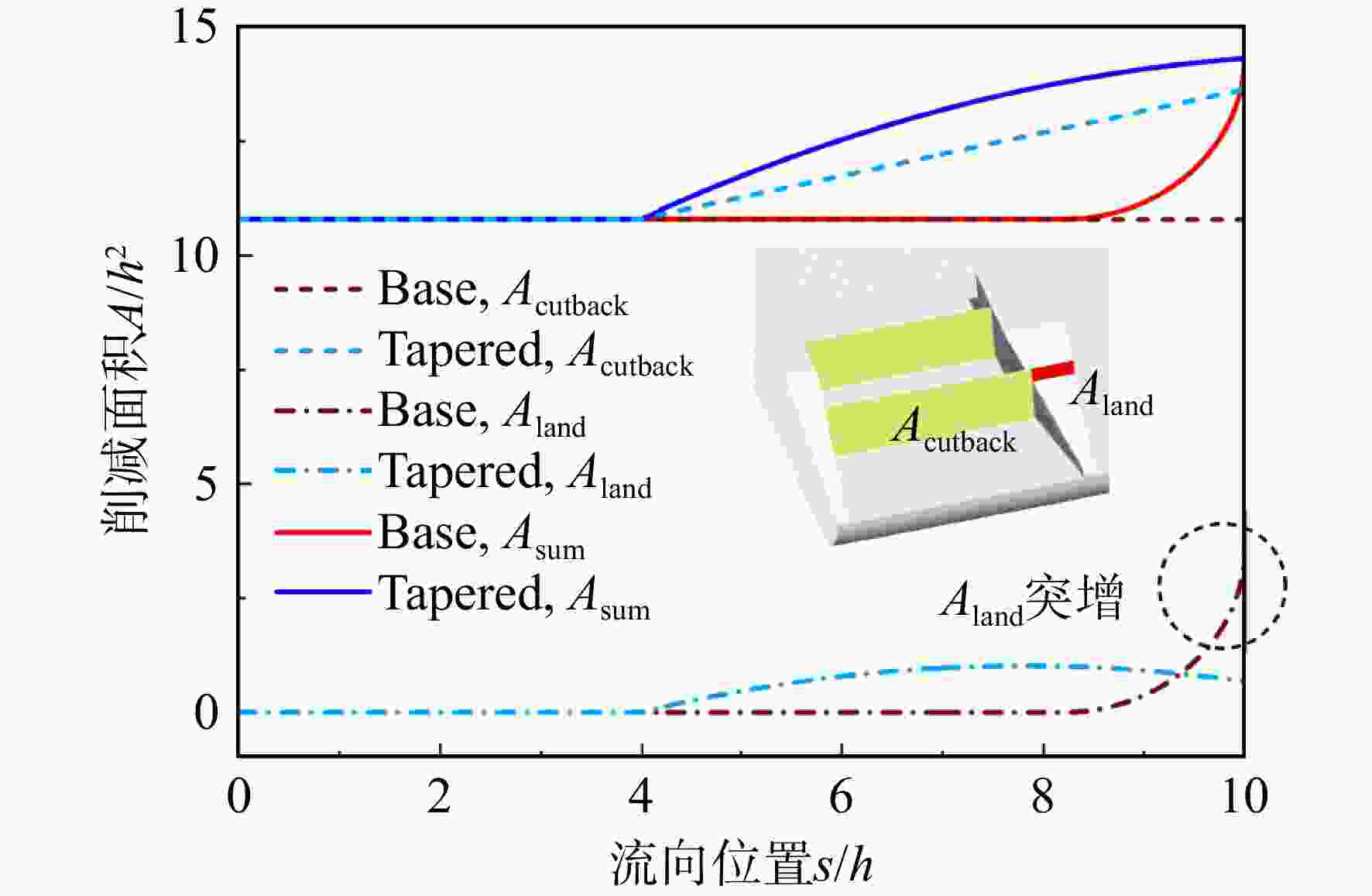
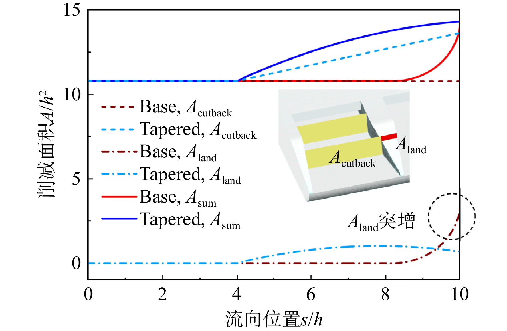
图 15 劈缝和筋板位置处的削减面积A/h2沿流向位置s的变化曲线
Figure 15. Curves of reduction area A/h2 at cutback and land regions along flow-direction coordinate s
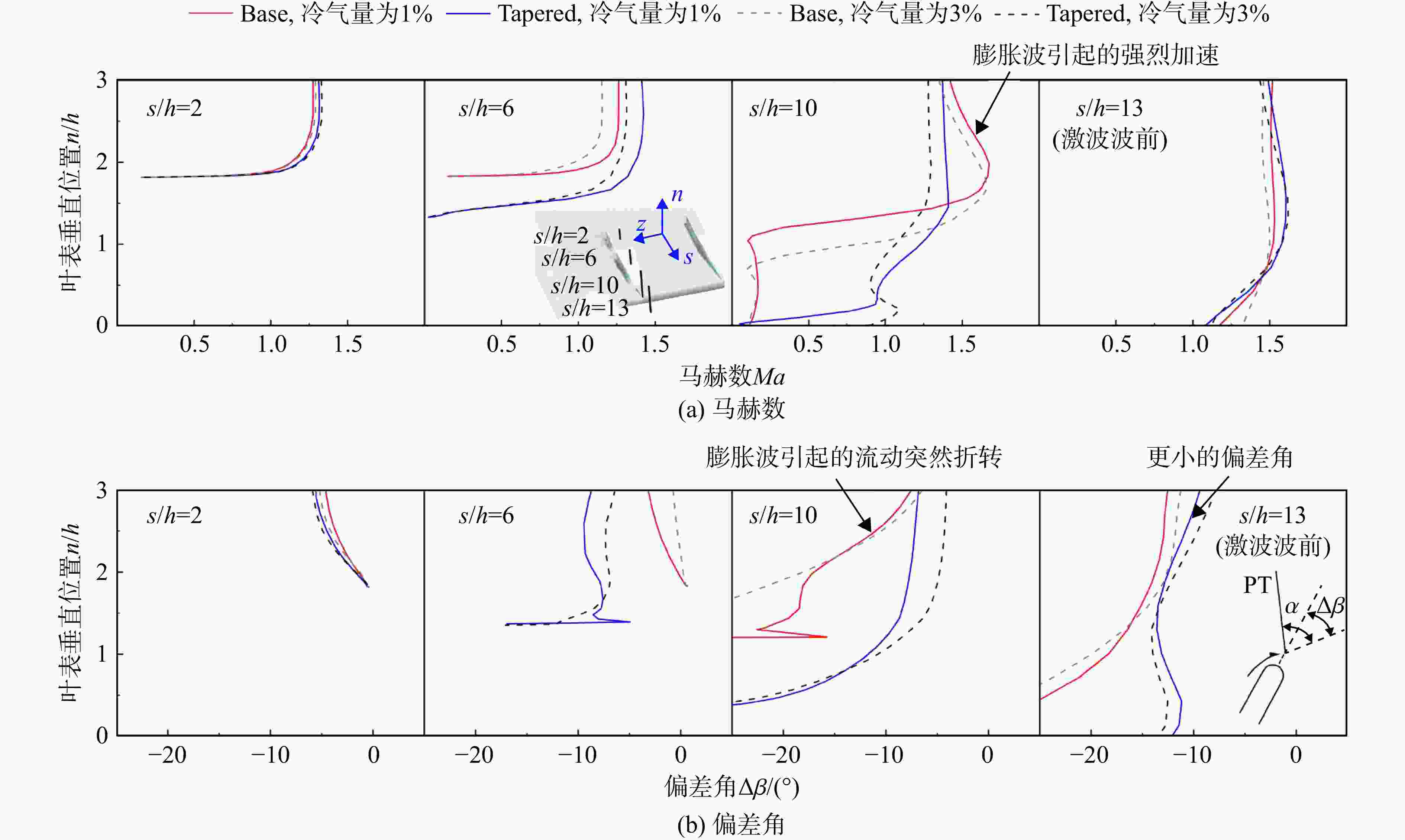
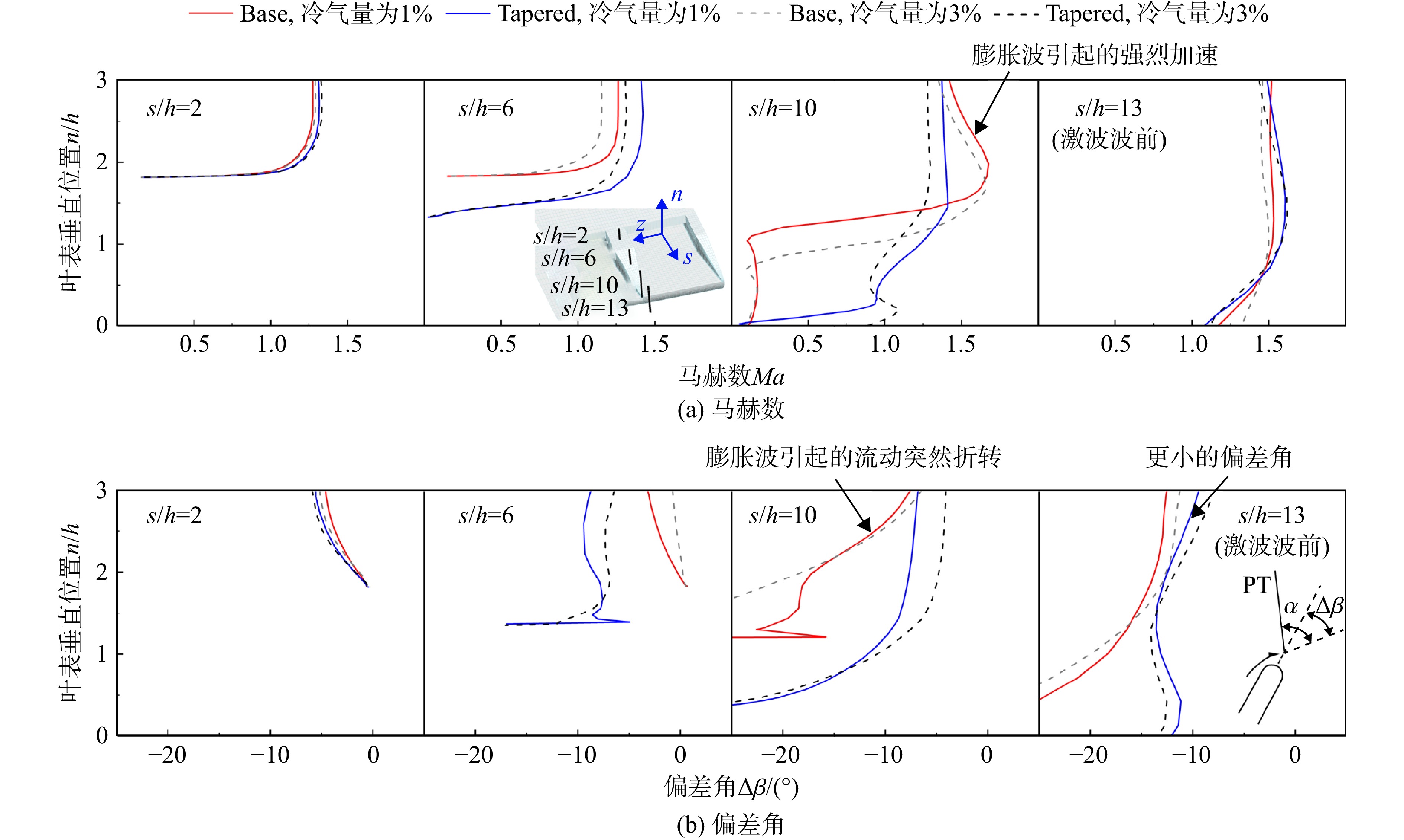
图 16 1%及3%冷气量时不同流向位置s处的Ma及Δβ沿垂直距离n的变化曲线
Figure 16. Curves of Ma and Δβ at different flow-direction coordinate s along vertical distance n under 1% and 3% coolant ratios
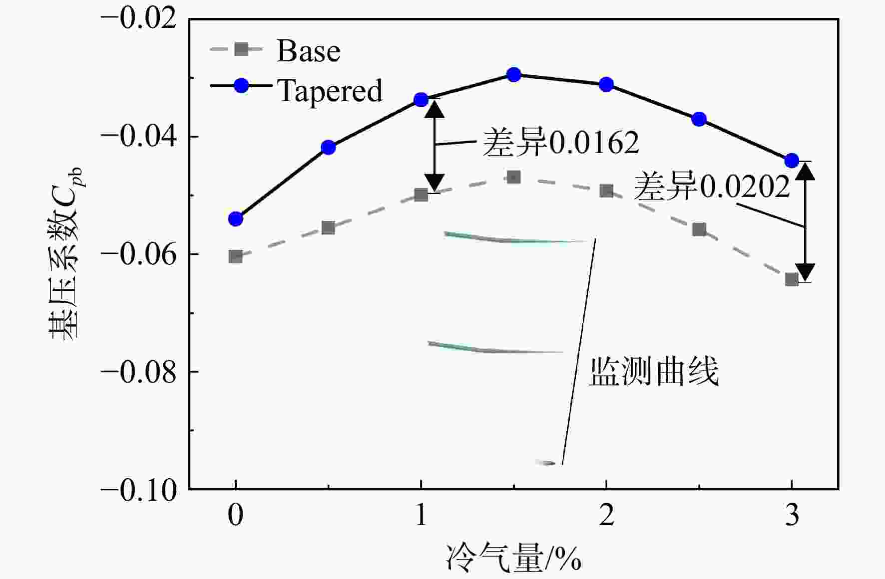
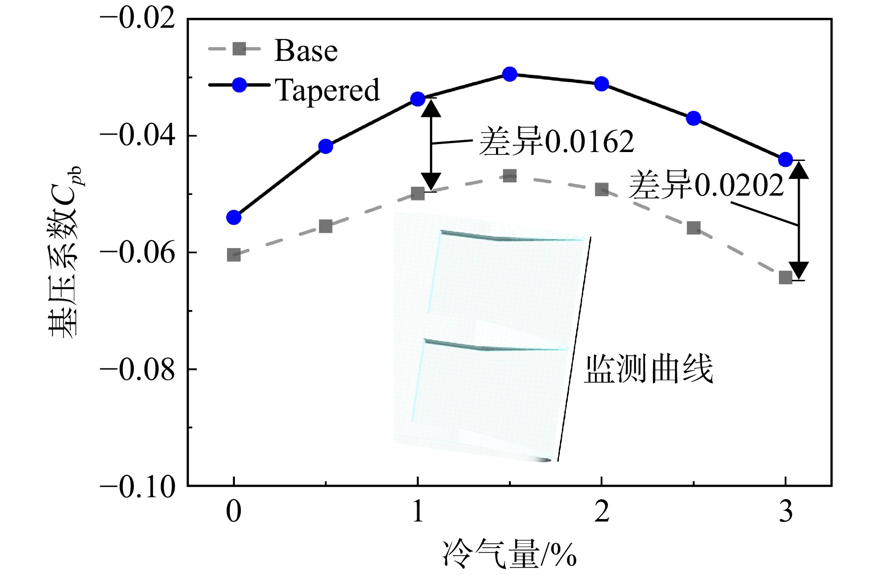
图 17 基压系数Cpb随冷气量变化曲线
Figure 17. Curves of base pressure ratio Cpb changing with coolant ratio
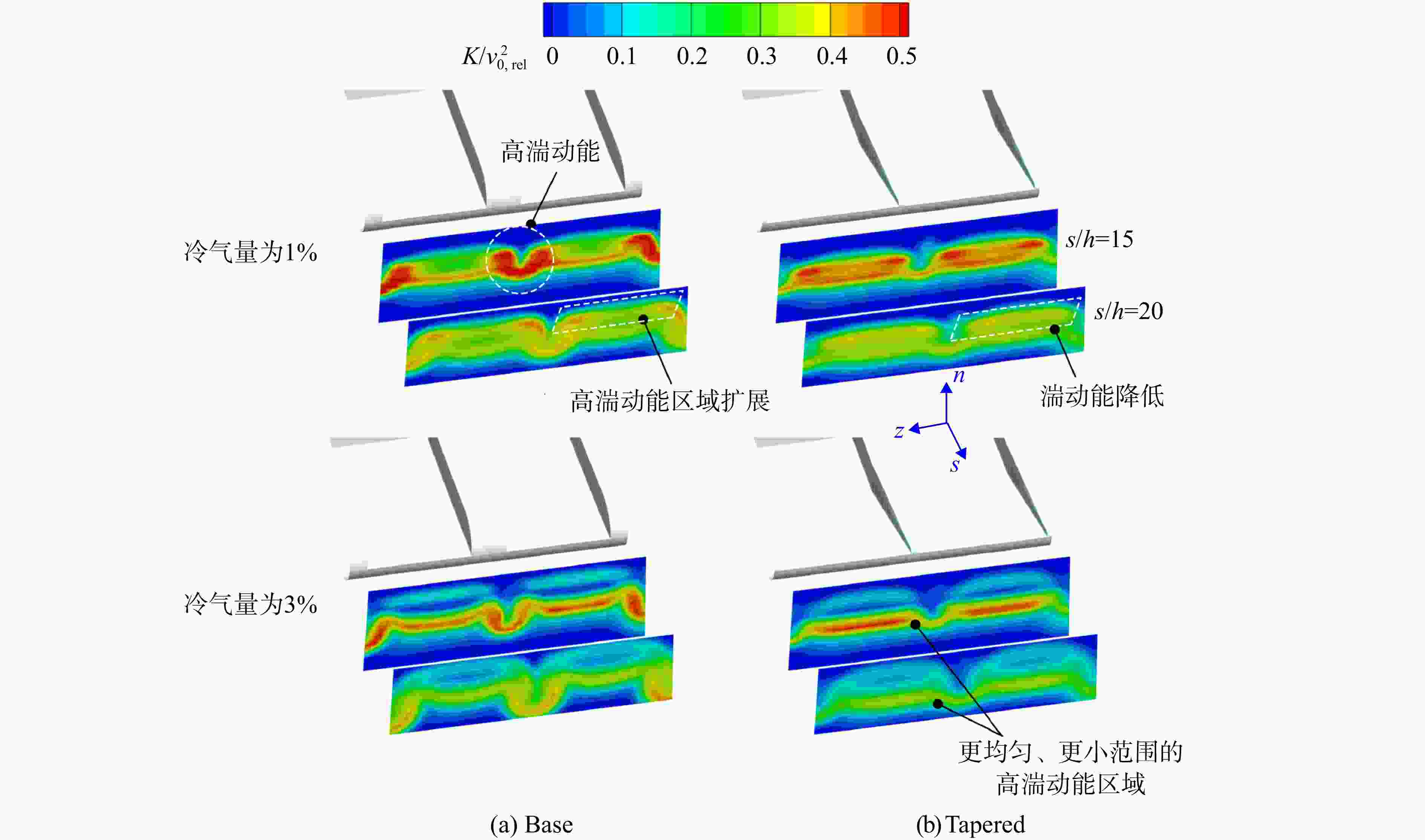
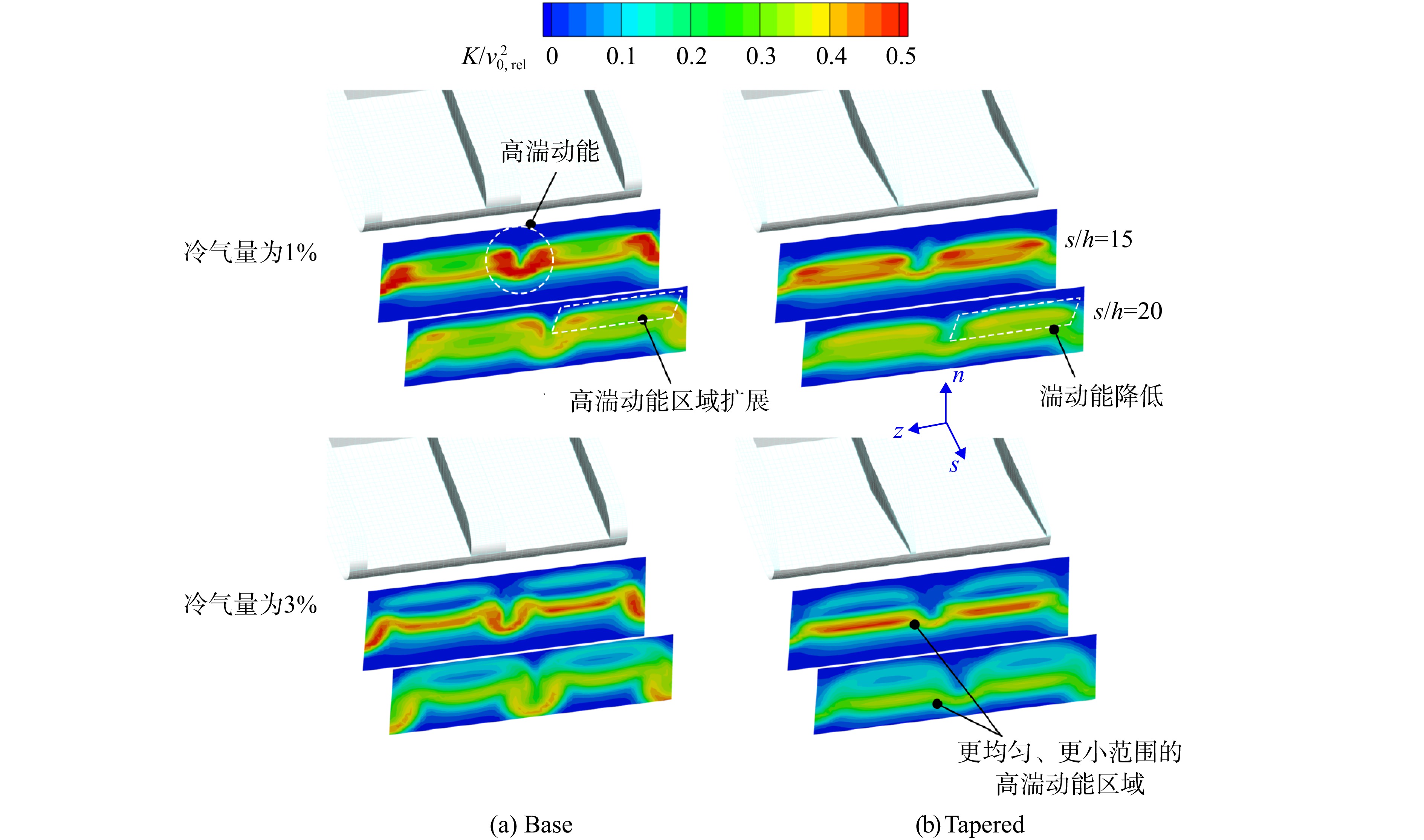
图 18 1%及3%冷气量时不同流向位置s处的湍动能K云图
Figure 18. Contours of turbulent kinetic energy K at different flow-direction coordinate s under 1% and 3% coolant ratios
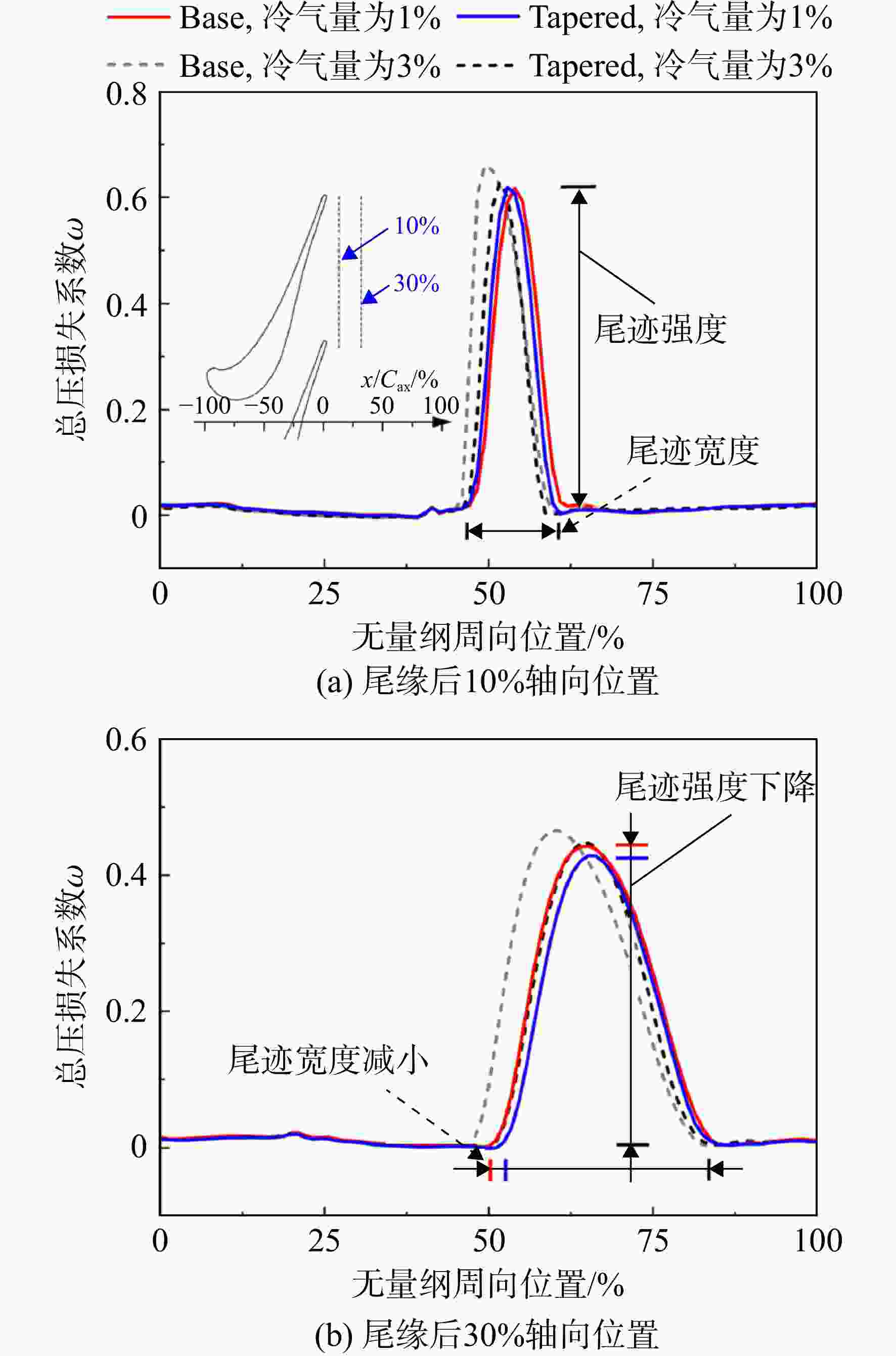
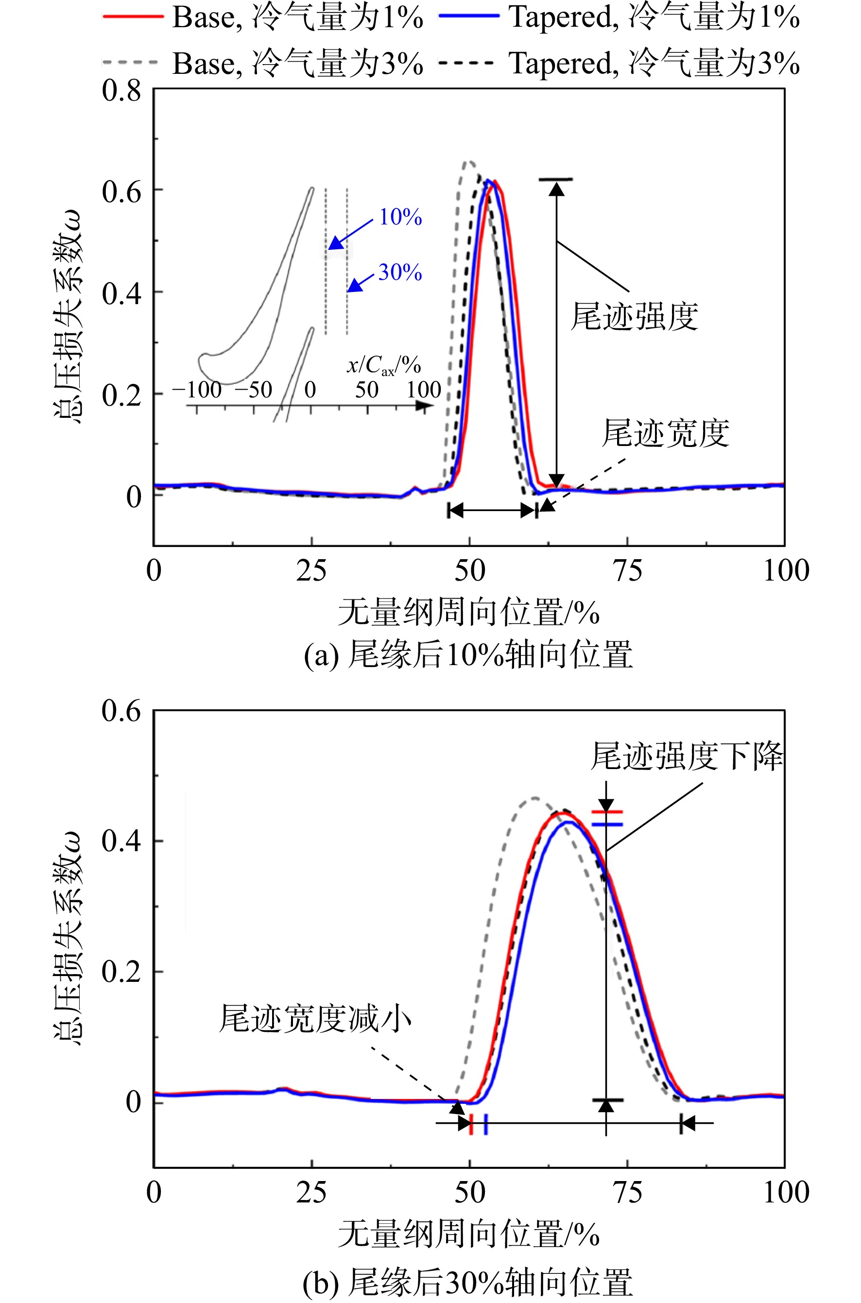
图 19 1%及3%冷气量时尾缘后不同位置处的相对总压损失系数ω沿周向变化曲线
Figure 19. Curves of relative total pressure loss coefficient ω downstream of trailing edge changing along circumferential location under 1% and 3% coolant ratios
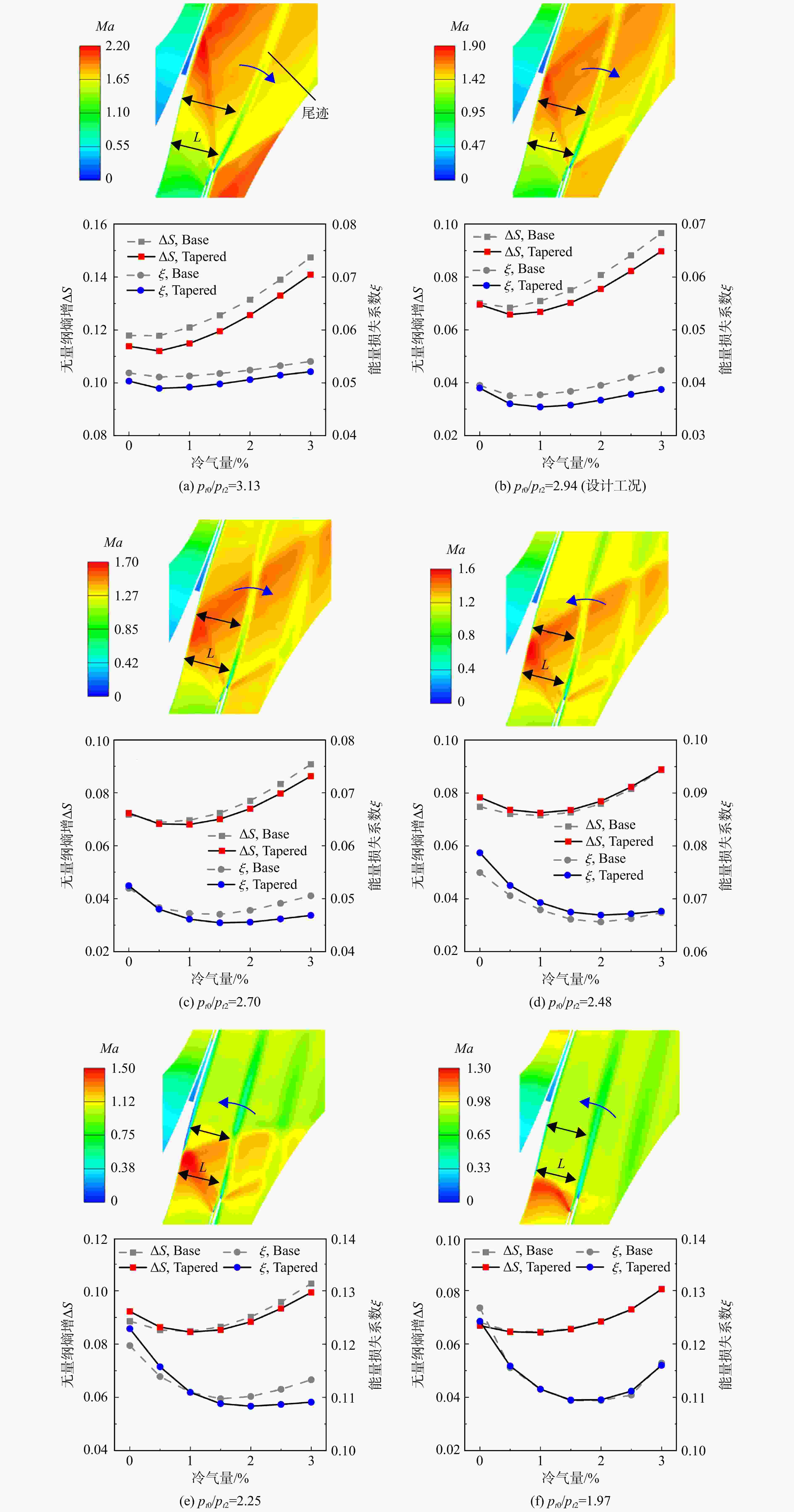
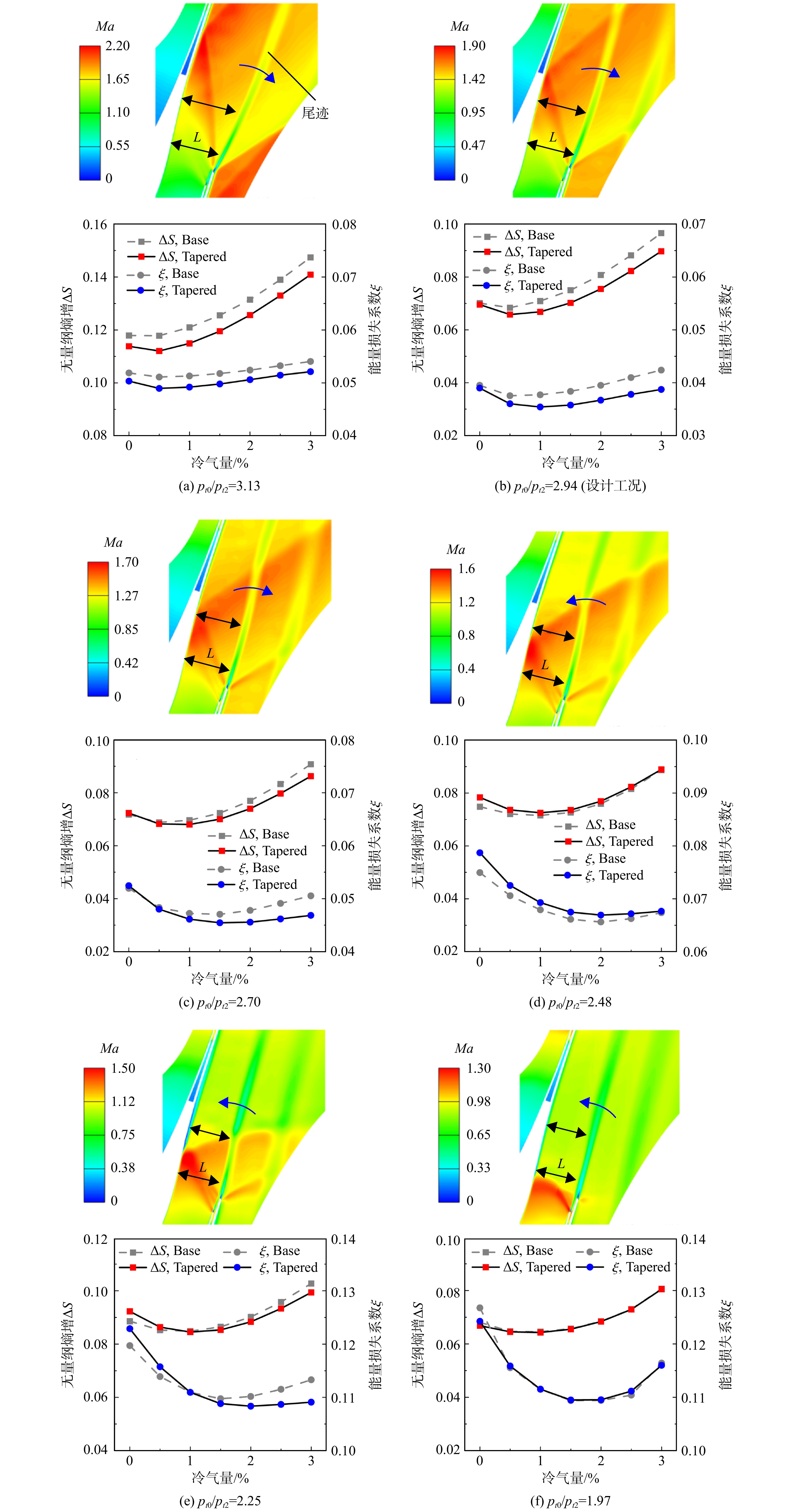
图 20 不同落压比下的马赫数云图及无量纲熵增ΔS0-2和能量损失系数ξ随冷气量的变化曲线
Figure 20. Contours of Ma and curves of dimensionless entropy rise ΔS0-2 and energy loss coefficient ξ changing with coolant ratio under different total-to-total pressure ratios
A 面积(mm2) σ 熵产率(W/(m3·K)) Cax 轴向弦长(46 mm) κ 比热比 Cpb 基压系数 ξ 能量损失系数 cp 比定压热容(J/(kg·K)) ω 总压损失系数 h 劈缝高度(0.5 mm) τij 黏性应力分量(Pa) I 湍流强度(%) 下标 K 湍动能(m2/s2) 0 计算域入口截面 k 热导率(W/(m·K)) 1 尾缘后0.3Cax处计算截面 Ma 马赫数 2 计算域出口截面 $ \dot{m} $ 质量流量(kg/s) c 冷气入口截面 n 劈缝垂直方向坐标(m) rel 旋转坐标系下的相对量 p 压强(Pa) t 滞止参数 R 空气常数(287 J/(kg·K)) 简称 s 劈缝流向坐标(m) CS 劈缝诱导激波(cutback shock) T 温度(K) EW 膨胀波(expansion wave) ui 速度分量(m/s) PT 内伸激波(pressure-side trailing-edge shock) x 轴向坐标(m) RPT 内伸激波反射波(reflection shock of pressure-side trailing-edge shock) z 叶片展向坐标(m) ΔS 无量纲熵增 Δβ 偏差角(°) ST 外伸激波(suction-side trailing-edge shock) η 气膜冷却效率  下载: 导出CSV
表 1 R1几何参数
Table 1. Geometric parameters of R1
参数 数值 进口几何角/(°) −45.85 出口几何角/(°) 72.96 安装角/(°) 57.20 轴向弦长/mm 46 前缘半径/mm 2.0 尾缘半径/mm 0.8
下载: 导出CSV
表 2 原型半劈缝结构几何参数
Table 2. Geometric parameters of base cutback structure
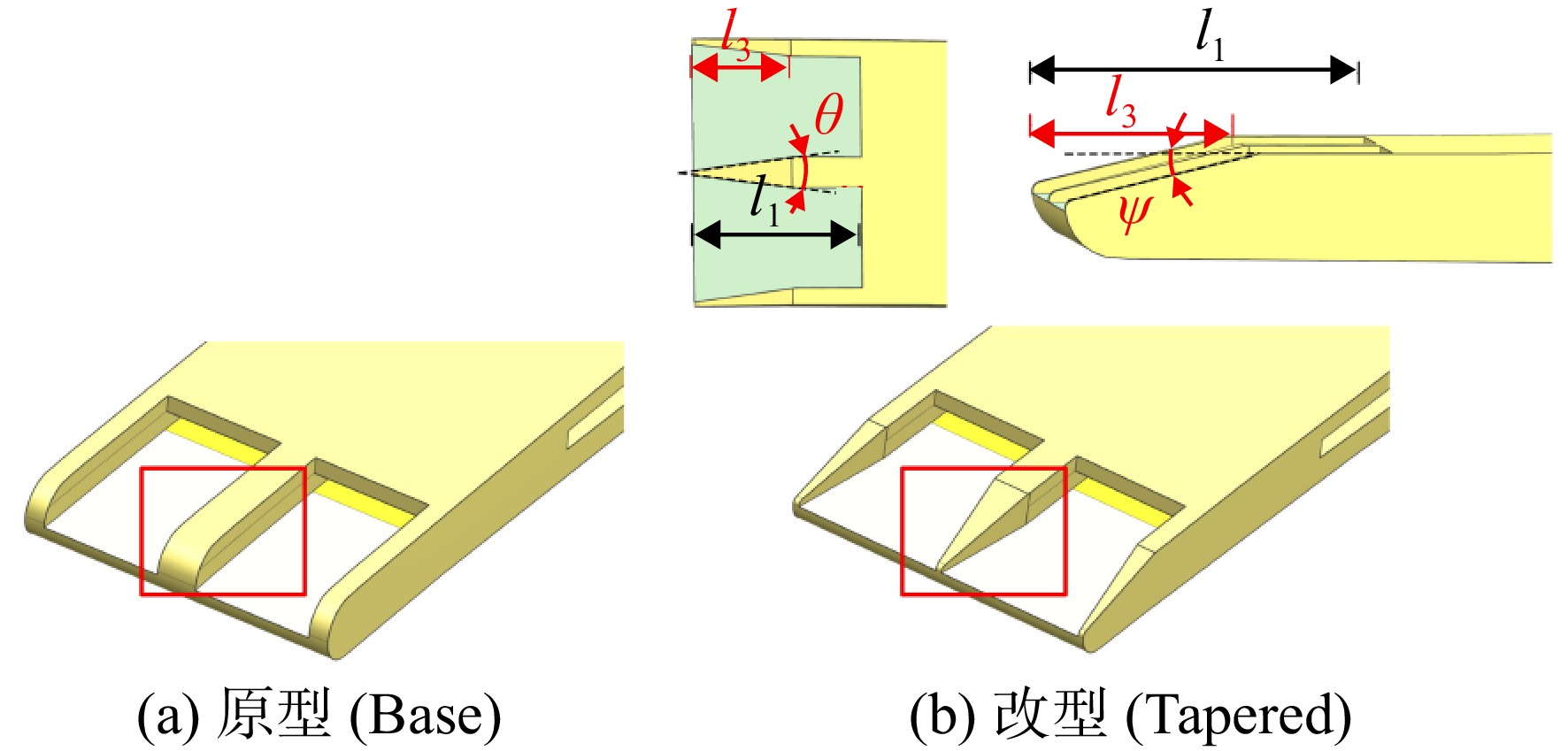
mm 参数 数值 劈缝高度h 0.5 唇口厚度t 0.4 劈缝长度l1 5 内部通道长度l2 5 劈缝宽度b 3 劈缝间距c 4
下载: 导出CSV
表 3 设计工况下的边界条件
Table 3. Boundary conditions of design point
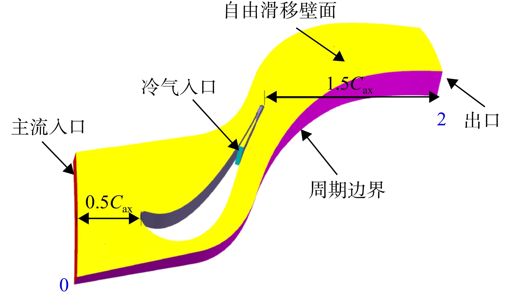
参数 数值 折合转速$ n\sqrt{288.15\;\text{K}/{T}_{t0}} $ /(r/min) 5531.2 主流进口总压与出口静压之比pt0/p2 5.242 冷气进口与主流进口总温比Ttc/Tt0 0.492 冷气与主流流量比($ {\dot{m}}_{\text{c}}/{\dot{m}}_{0} $)/% 0~3 湍流强度I/% 10
下载: 导出CSV
-
[1] Zhao Wei, Luo Weiwei, Zhao Qingjun, et al. Investigation on the reduction of trailing edge shock losses for a highly loaded transonic turbine[C]//ASME Turbo Expo 2016: Turbomachinery Technical Conference and Exposition. Seoul, South Korea: American Society of Mechanical Engineers, 2016: V02BT38A005. [2] Denton J D. Loss the 1993 IGTI scholar lecture: loss mechanisms in turbomachines[J]. Journal of Turbomachinery, 1993, 115(4): 621-656. doi: 10.1115/1.2929299 [3] Schobeiri M T, Pappu K. Optimization of trailing edge ejection mixing losses: a theoretical and experimental study[J]. Journal of Fluids Engineering, 1999, 121(1): 118-125. doi: 10.1115/1.2821991 [4] Gao Jie, Wei Ming, Fu Weiliang, et al. Experimental and numerical investigations of trailing edge injection in a transonic turbine cascade[J]. Aerospace Science and Technology, 2019, 92: 258-268. doi: 10.1016/j.ast.2019.05.069 [5] Rehder H J. Investigation of trailing edge cooling concepts in a high pressure turbine cascade: aerodynamic experiments and loss analysis[J]. Journal of Turbomachinery, 2012, 134(5): 051029. doi: 10.1115/1.4004748 [6] Sieverding C H, Stanislas M, Snoeck J. The base pressure problem in transonic turbine cascades[J]. Journal of Engineering for Power, 1980, 102(3): 711-718. [7] Sieverding C H. The influence of trailing edge ejection on the base pressure in transonic turbine cascades[J]. Journal of Engineering for Power, 1983, 105(2): 215-222. doi: 10.1115/82-gt-50 [8] Raffel M, Kost F. Investigation of aerodynamic effects of coolant ejection at the trailing edge of a turbine blade model by PIV and pressure measurements[J]. Experiments in Fluids, 1998, 24(5): 447-461. [9] Saracoglu B H, Paniagua G, Rambaud P. Blunt trailing edge cooling effects at supersonic regime[C]//45th AIAA/ASME/SAE/ASEE Joint Propulsion Conference & Exhibit. Denver, Colorado: AIAA, 2009: AIAA 2009-5105. [10] Saracoglu B H, Paniagua G, Salvadori S, et al. Trailing edge shock modulation by pulsating coolant ejection[J]. Applied Thermal Engineering, 2012, 48: 1-10. [11] Cunha F J, Chyu M K. Trailing-edge cooling for gas turbines[J]. Journal of Propulsion and Power, 2006, 22(2): 286-300. doi: 10.2514/1.20898 [12] Denton J D, Xu L. The trailing edge loss of transonic turbine blades[J]. Journal of Turbomachinery, 1990, 112(2): 277-285. [13] Zhou Chao, Hodson H, Himmel C. The effects of trailing edge thickness on the losses of ultrahigh lift low pressure turbine blades[J]. Journal of Turbomachinery, 2014, 136(8): 081011. [14] Uzol O, Camci C, Glezer B. Aerodynamic loss characteristics of a turbine blade with trailing edge coolant ejection: Part 1 effect of cut-back length, spanwise rib spacing, free-stream Reynolds number, and chordwise rib length on discharge coefficients[J]. Journal of Turbomachinery, 2001, 123(2): 238-248. [15] Uzol O, Camci C. Aerodynamic loss characteristics of a turbine blade with trailing edge coolant ejection: Part 2 external aerodynamics, total pressure losses, and predictions[J]. Journal of Turbomachinery, 2001, 123(2): 249-257. [16] 杨林, 曾军, 谭洪川, 等. 大膨胀比跨声速涡轮流动结构及损失的数值研究[J]. 推进技术, 2014, 35(5): 632-640. Yang Lin, Zeng Jun, Tan Hongchuan, et al. Numerical study on flow structure and loss of large expansion ratio transonic turbine[J]. Journal of Propulsion Technology, 2014, 35(5): 632-640. (in ChineseYang Lin, Zeng Jun, Tan Hongchuan, et al. Numerical study on flow structure and loss of large expansion ratio transonic turbine[J]. Journal of Propulsion Technology, 2014, 35(5): 632-640. (in Chinese) [17] 侯伟涛, 乔渭阳. 尾缘冷却跨声速涡轮气动特性的数值模拟[J]. 推进技术, 2010, 31(5): 567-571. Hou Weitao, Qiao Weiyang. Numerical simulation of the trailing edge cooled transonic turbine aerodynamic characteristic[J]. Journal of Propulsion Technology, 2010, 31(5): 567-571. (in ChineseHou Weitao, Qiao Weiyang. Numerical simulation of the trailing edge cooled transonic turbine aerodynamic characteristic[J]. Journal of Propulsion Technology, 2010, 31(5): 567-571. (in Chinese) [18] Wang Y F, Zhou X, Liu X, et al. Influence of trailing edge coolant ejection rate and cut-back length on energy loss and shockwave intensity of a transonic turbine blade[C]//ASME Turbo Expo 2016: Turbomachinery Technical Conference and Exposition. Seoul, South Korea: American Society of Mechanical Engineers, 2016: V02BT38A030. [19] Yang Zifeng, Hu Hui. Study of trailing-edge cooling using pressure sensitive paint technique[J]. Journal of Propulsion and Power, 2011, 27(3): 700-709. [20] Yang Zifeng, Johnson M, Posada N, et al. Film cooling on the geometrically modified trailing edge model of gas turbine blade[J]. Journal of Turbomachinery, 2019, 141(9): 091012. [21] Du Wei, Luo Lei, Wang Songtao, et al. Film cooling in the trailing edge cutback with different land shapes and blowing ratios[J]. International Communications in Heat and Mass Transfer, 2021, 125: 105311. [22] Benson M, Yapa S D, Elkins C, et al. Experimental-based redesigns for trailing edge film cooling of gas turbine blades[J]. Journal of Turbomachinery, 2013, 135(4): 041018. [23] Ling J L, Elkins C J, Benson M J, et al. Measurements of a trailing edge slot film cooling geometry designed for reduced coolant flowrate and high surface effectiveness[C]//ASME Turbo Expo 2013: Turbine Technical Conference and Exposition. San Antonio, US: American Society of Mechanical Engineers, 2013: V03BT13A009. [24] Ling Julia, Yapa S D, Benson M J, et al. Three-dimensional velocity and scalar field measurements of an airfoil trailing edge with slot film cooling: the effect of an internal structure in the slot[J]. Journal of Turbomachinery, 2013, 135(3): 031018. [25] Ling Julia, Rossi R, Eaton J K. Near wall modeling for trailing edge slot film cooling[J]. Journal of Fluids Engineering, 2015, 137(2): 021103. [26] Ling Julia, Elkins C J, Eaton J K. The effect of land taper angle on trailing edge slot film cooling[J]. Journal of Turbomachinery, 2015, 137(7): 071003. [27] Zhao Wei, Wu Bing, Xu Jianzhong. Aerodynamic design and analysis of a multistage vaneless counter-rotating turbine[J]. Journal of Turbomachinery, 2015, 137(6): 061008. [28] Zhou Qinghui, Zhao Wei, Sui Xiuming, et al. A shock loss reduction method using a concave suction side profile for a zero inlet swirl turbine rotor[J]. Journal of Turbomachinery, 2022, 144(11): 111010. -

 点击查看大图

计量
- 文章访问数: 624
- HTML浏览量: 267
- PDF量: 51
- 被引次数: 0