






Load distribution model and experimental validation for APU installation system based on Gap element
-
摘要:
以某型飞机辅助动力装置(APU)安装系统静强度设计为例,提出了基于Gap单元APU安装系统分载模型,分载模型考虑了APU本体、APU安装拉杆与减振器连接接触的非线性。对比APU安装系统减振器实体有限元模型计算结果,说明基于Gap单元APU安装系统分载模型的有效性。同时建立了APU安装静力试验方案,为保证仿真模型与试验模型高度一致,对APU安装拉杆进行试验标定、对减振器刚度进行试验测试。筛选严酷工况,通过与试验结果对比,拉杆应变在100 με以上,基于Gap单元APU安装系统分载模型计算拉杆应变与试验结果最小差异在4.6%、最大差异在7.5%,实体建模计算拉杆应变与试验结果最小差异在9.4%、最大差异在11.2%,进一步说明基于Gap单元APU安装系统分载模型的准确性。基于Gap单元APU安装系统分载模型提高了APU安装系统分载量值计算精度和建模效率,为减振器组合件之间的接触建模提供了一种有效的建模方法。
Abstract:Taking the static strength design of an auxiliary power unit (APU) installation system for a specific aircraft model as an example, a load distribution model based on Gap elements was proposes. The nonlinearity in the contact between the APU body, mounting tie rods, and vibration isolators were considered. Comparisons with the results from the solid finite element model of the APU installation system vibration isolator demonstrated the effectiveness of the Gap element-based load distribution model. Concurrently a static test plan for the APU installation system was established. To ensure high consistency between the simulation and test models, the APU mounting tie rods were calibrated, and the stiffness of the vibration isolators was tested. Under selected severe load cases and comparing with the test results, the strain of the tie rod was above 100 με. The minimum difference between the strain of the tie rod calculated by Gap element-based load distribution model of the APU mounting system and the test results was 4.6%, and the maximum difference was 7.5%. The minimum difference between the strain of the tie rod calculated by the solid modeling and the test results was 9.4%, and the maximum difference was 11.2%. Comparisons with test results further illustrated the accuracy of the Gap element-based load distribution model for the APU installation system. This model improved the calculation accuracy of load distribution values and modeling efficiency for the APU installation system, providing an effective modeling approach for simulating contact interactions between vibration isolator assemblies.
-
Key words:
- auxiliary power unit (APU) /
- Gap element /
- load distribution model /
- static test /
- modeling approach
-
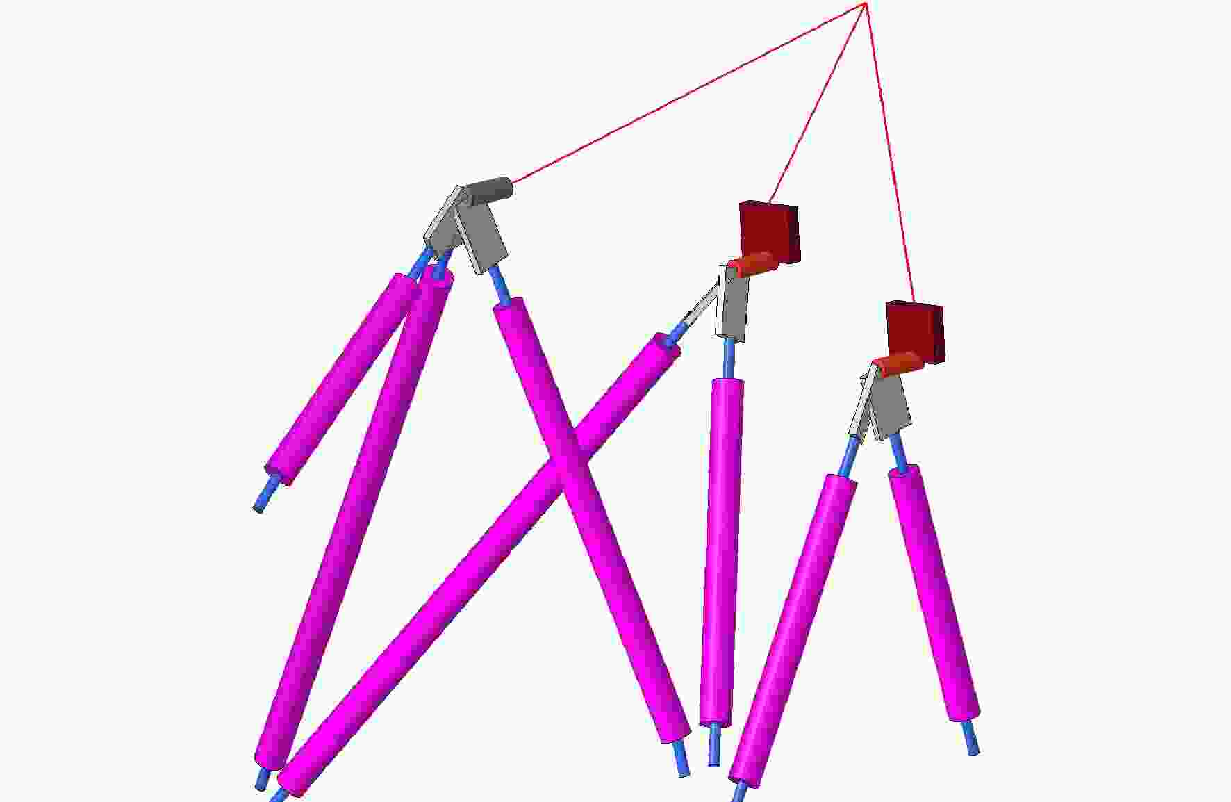
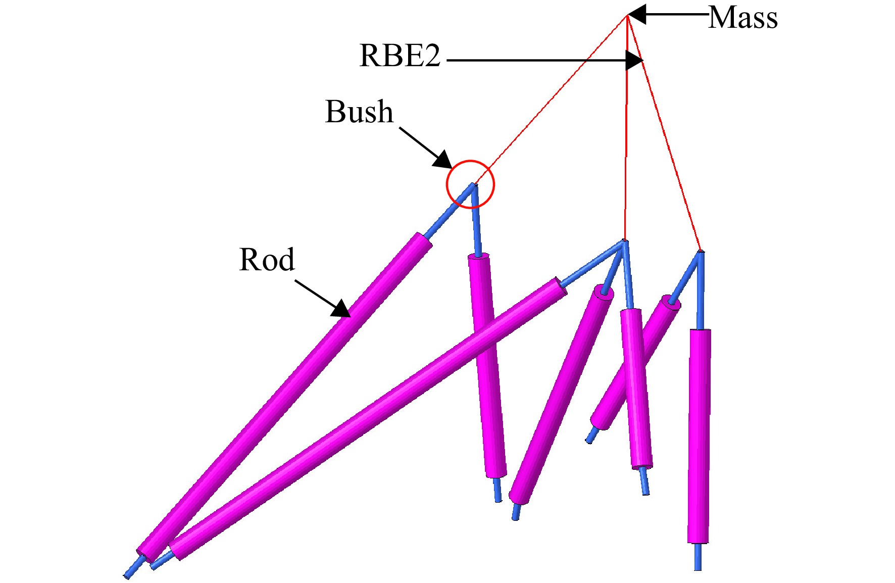
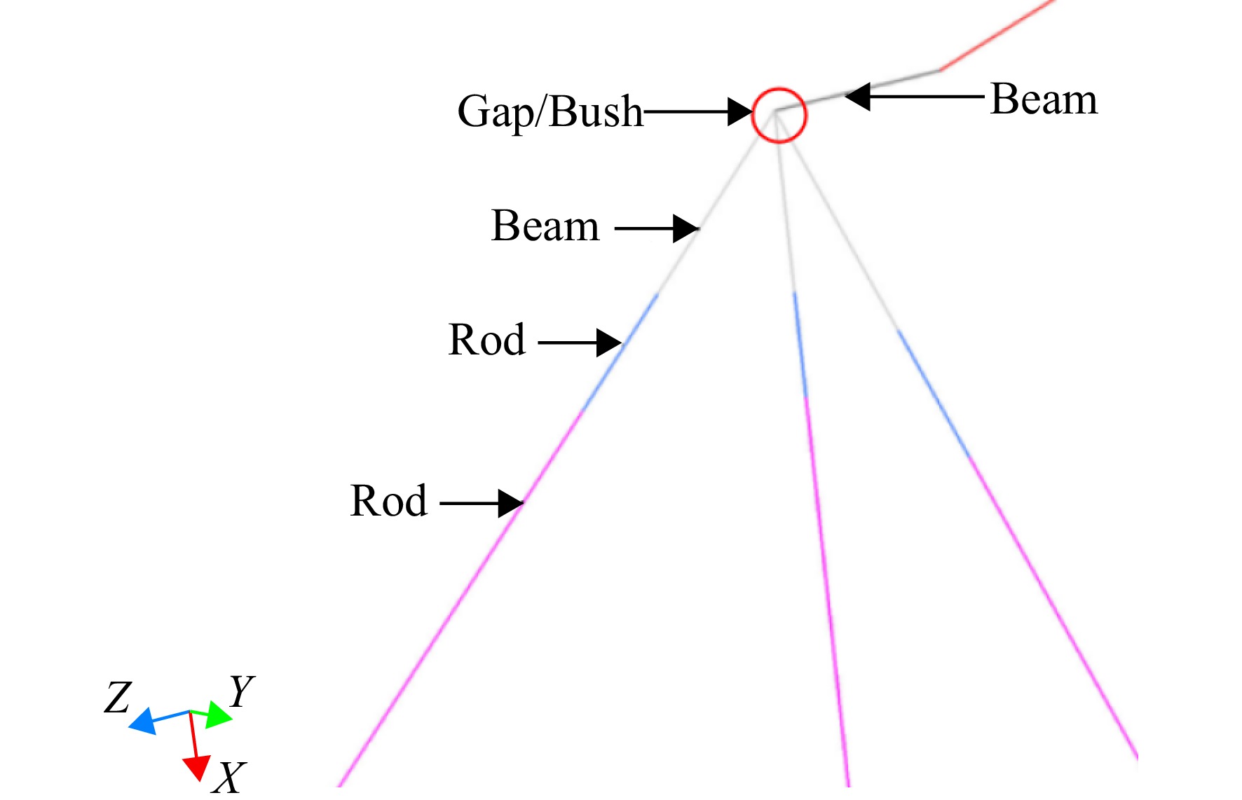
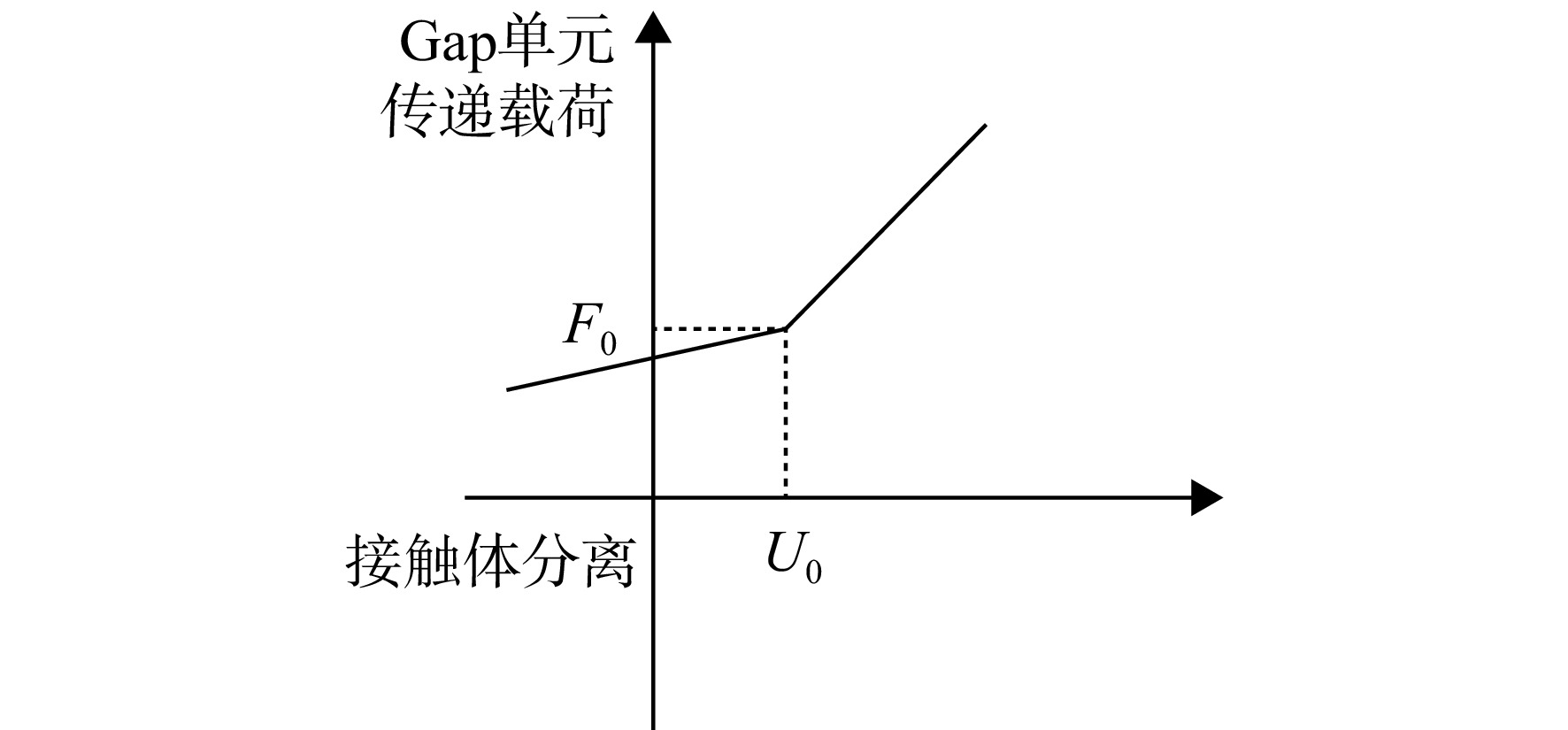
图 4 APU安装系统分载非线性简化模型
Figure 4. Simplified nonlinear model of the load distribution APU installation

图 9 APU假件重心坐标测量
Figure 9. Measurement of the center of gravity coordinates of APU dummy component

图 10 拉杆应变片贴片位置示意图
Figure 10. Schematic diagram of strain gauge mounting location on rod
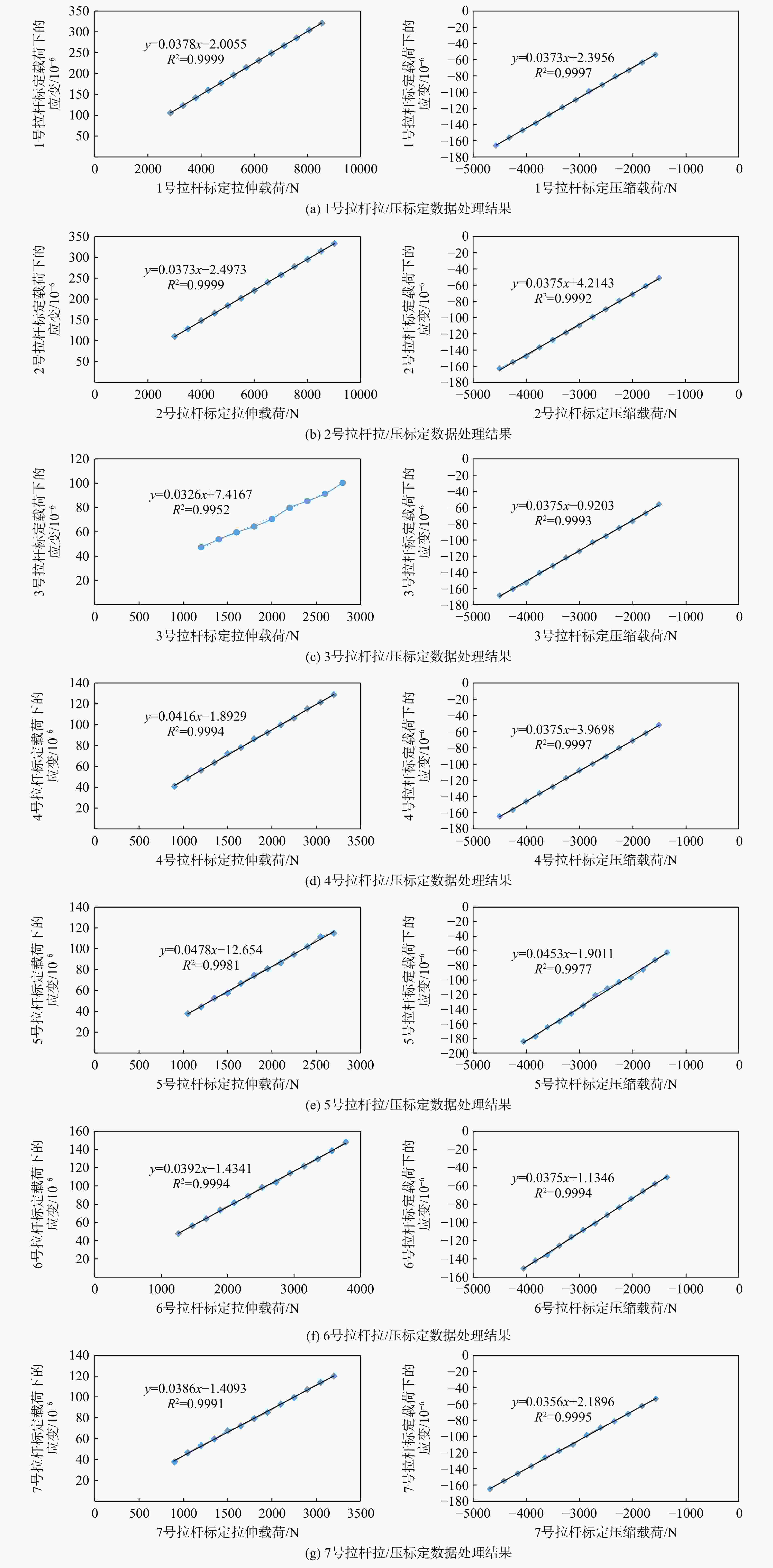
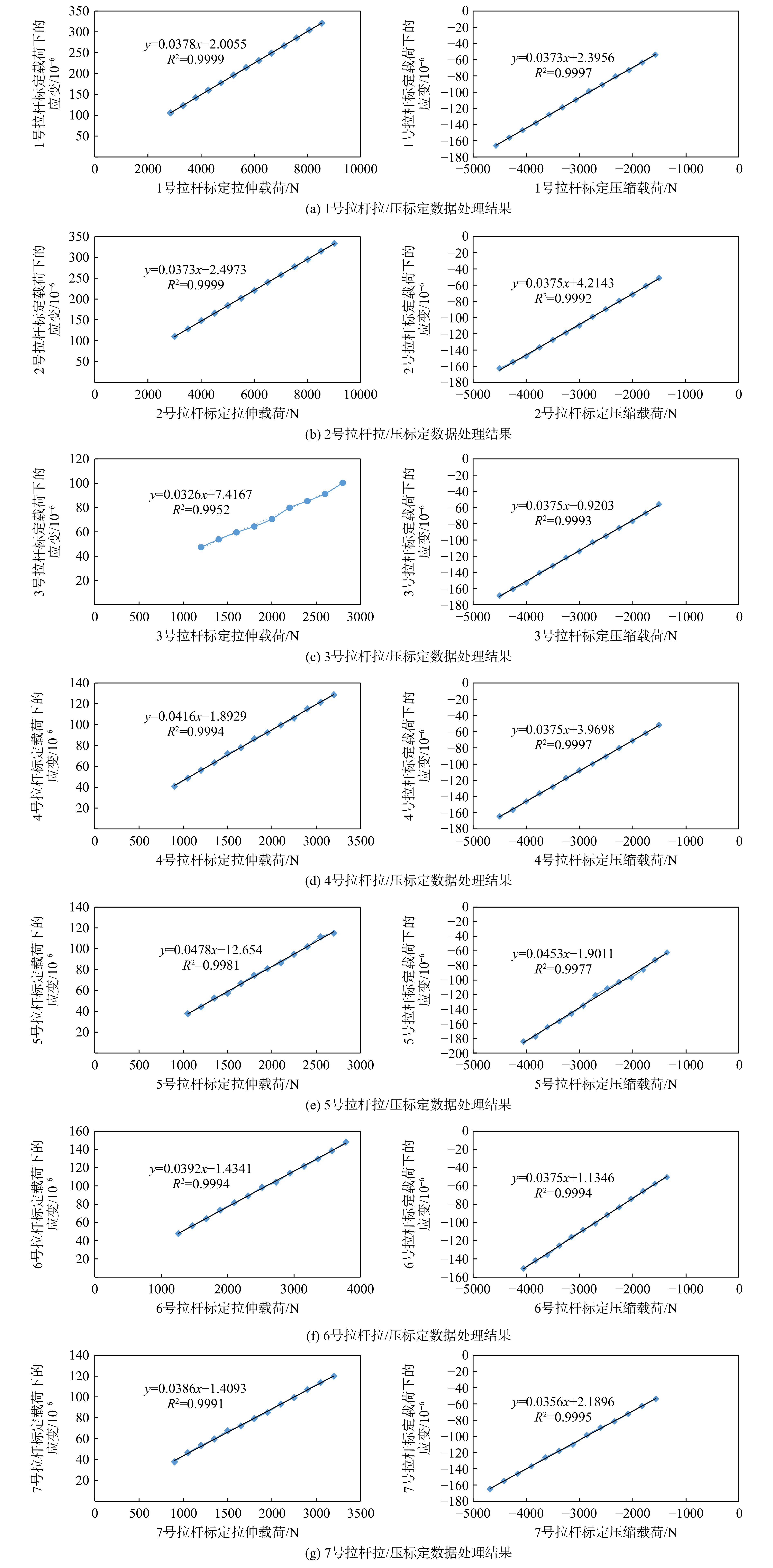
图 11 拉杆载荷标定试验应变数据处理
Figure 11. Strain data processing for the tie-rod load calibration test
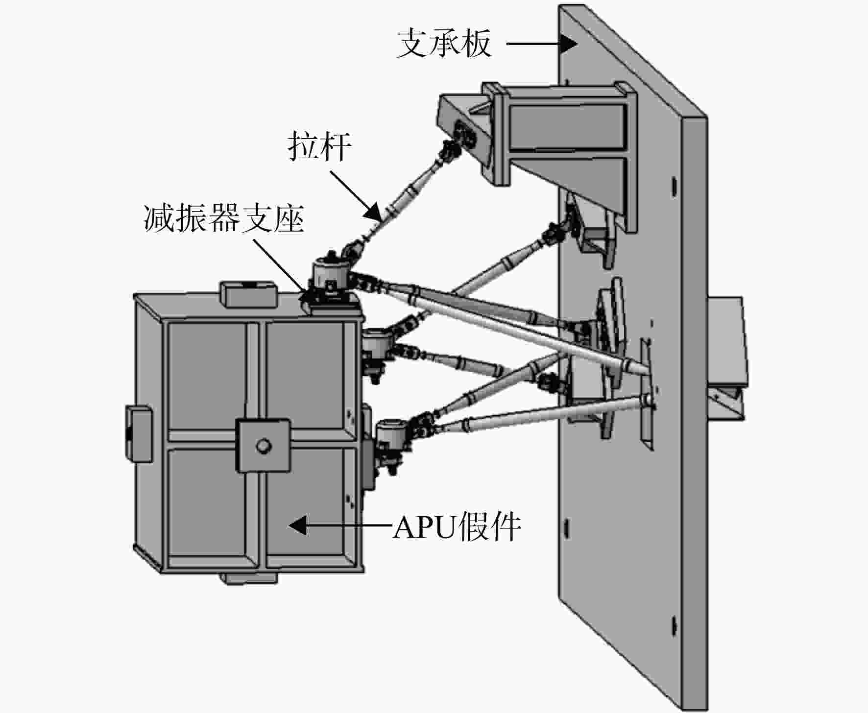
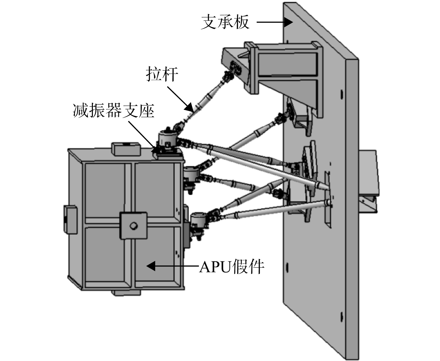
图 12 APU安装系统静力试验装置示意图
Figure 12. Schematic diagram of the static test setup for the APU installation

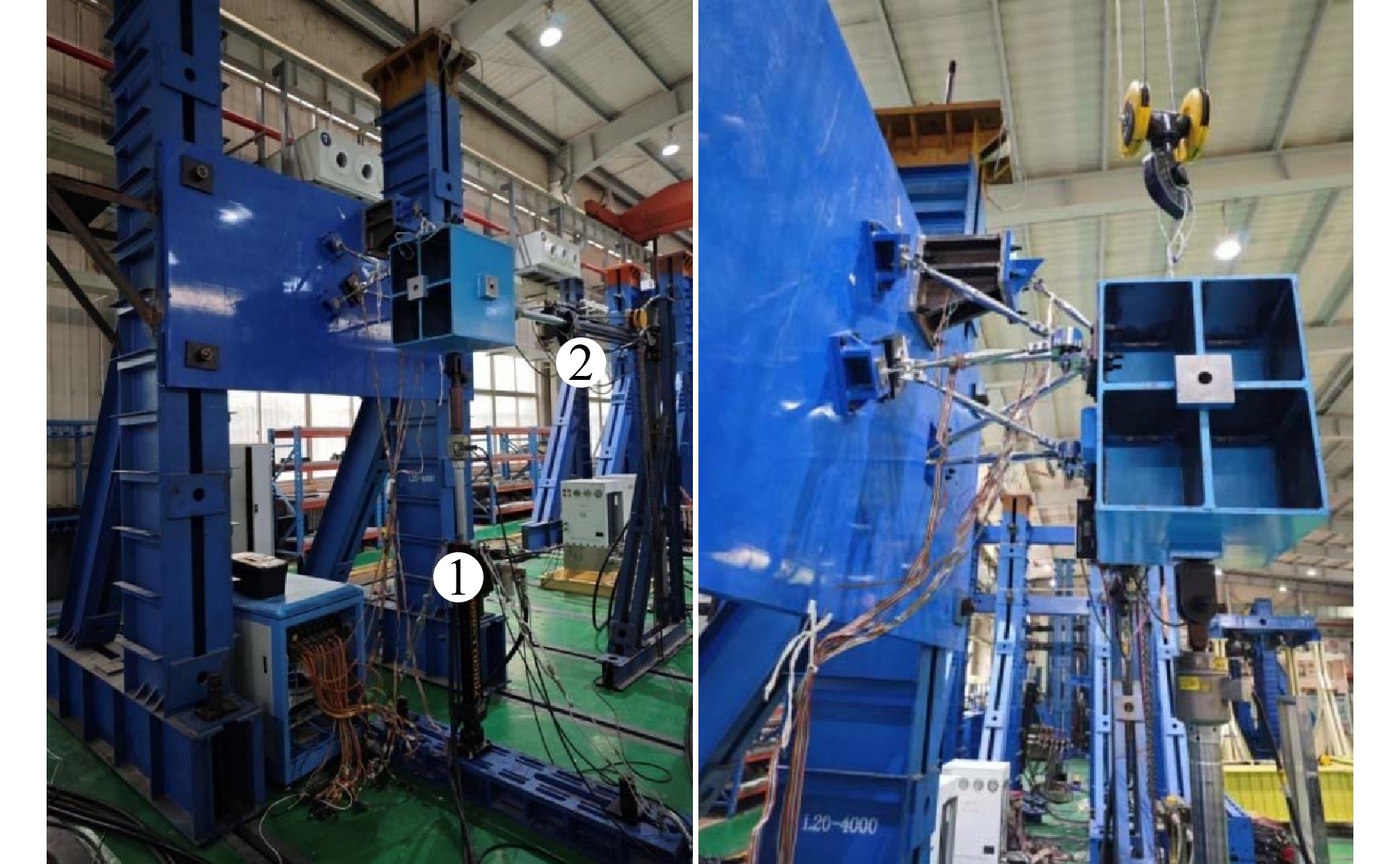
图 13 APU安装系统静力试验装置图
Figure 13. Diagram of the loading device for the APU installation system static test
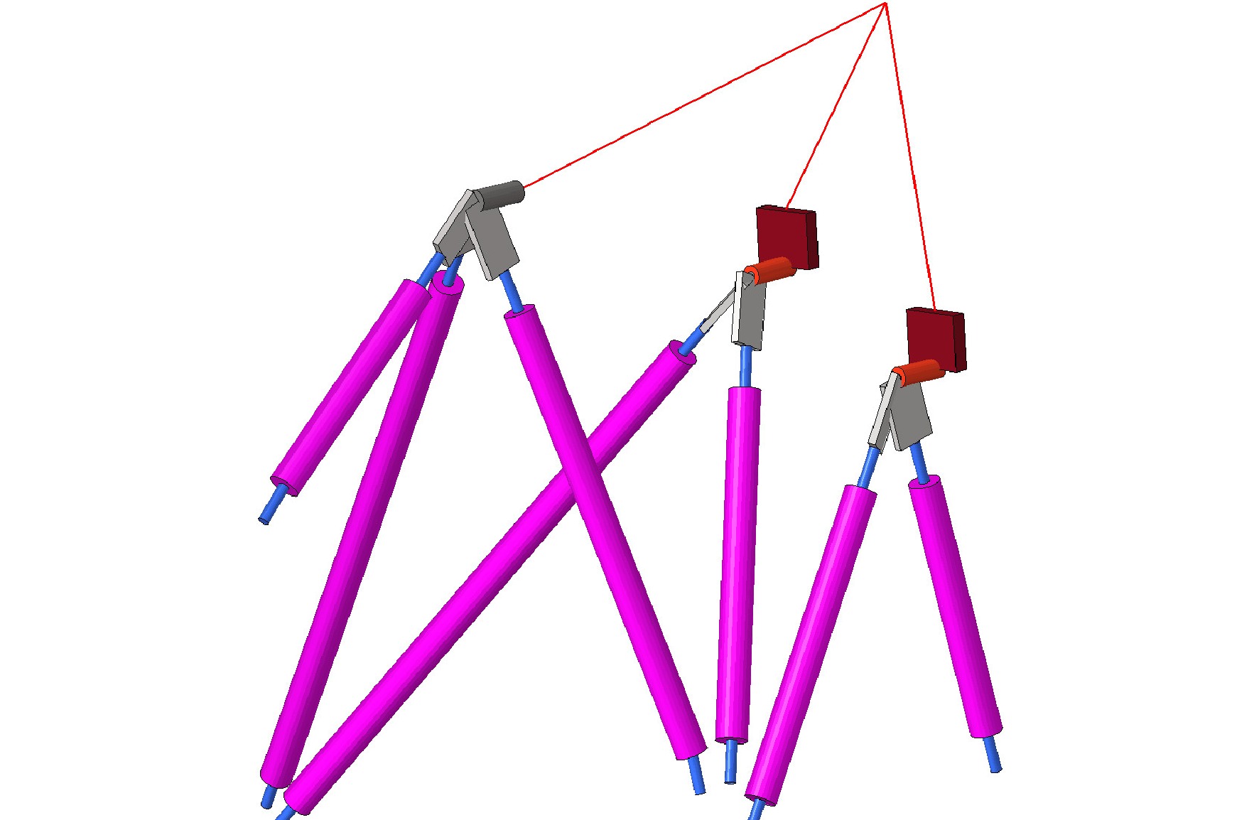
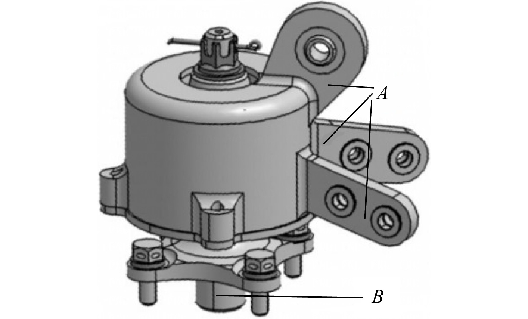
表 1 减振器结构简化
Table 1. Simplified model of the vibration isolator
模型类别 上减振器 前减振器 后减振器 三维
数模


有限元
模型


 下载: 导出CSV
表 2 APU安装系统零部件材料力学性能数据表
Table 2. Material mechanical property data table for APU installation components
零部件名称 材料牌号 弹性模型/
GPa抗拉强度/
MPa拉杆 不锈钢321 200 724 拉杆支座 不锈钢17-4PH-H1025 200 1068
下载: 导出CSV
表 3 APU安装拉杆轴向载荷最大所对应的载荷工况
Table 3. Load cases corresponding to maximum axial load of the APU installation tie rod
序号 加速度量值 向前 向后 向上 向下 1 9g 2 1.67g 3 1.05g 5.13g 4 0.61g 12.18g
下载: 导出CSV
表 4 减振器与拉杆、APU安装节非线性接触对拉杆分载影响对比表(单位加速度载荷工况)
Table 4. Comparison table of nonlinear contact effects on APU installation tie rod load distribution (unit acceleration load case)
参数 模型 载荷
工况拉杆编号 1 2 3 4 5 6 7 载荷/N 模型-1 向前1g 460 −395 −596 75 −401 222 53 向左1g −898 494 1335 −437 454 −412 −255 向上1g −945 − 1279 486 440 104 152 662 模型-2 向前1g 470 −390 −600 90 −410 230 40 向左1g −970 540 1240 −350 460 −470 −170 向上1g −910 − 1250 490 450 70 150 680 模型-2与模型-1
的相对误差/%向前1g 2.17 −1.27 0.67 20.00 2.24 3.60 −24.53 向左1g 8.02 9.31 −7.12 −19.91 1.32 14.08 −33.33 向上1g −3.70 −2.27 0.82 2.27 −32.69 −1.32 2.72 注:模型-1未考虑减振器与拉杆、APU本体安装节的非线性接触的简化模型;模型-2通过Gap单元模拟减振器与拉杆、APU本体安装节的非线性接触。
下载: 导出CSV
表 5 减振器与拉杆、APU安装节非线性接触对拉杆分载影响对比表(向前9g工况)
Table 5. Comparison table of nonlinear contact effects on APU installation tie rod load distribution (forward 9g load case)
参数 模型 载荷
工况拉杆编号 1 2 3 4 5 6 7 载荷/N 模型-1 向前9g 4140 − 3555 − 5364 675 − 3609 1998 477 模型-2 向前9g 4223 − 3496 − 5542 817 − 3721 2057 674 模型-2与模型-1
的相对误差/%向前9g 2.0 −1.61 3.32 21.04 3.10 2.95 −41.29 注:模型-1未考虑减振器与拉杆、APU本体安装节的非线性接触的简化模型;模型-2通过Gap单元模拟减振器与拉杆、APU本体安装节的非线性接触。
下载: 导出CSV
表 6 APU假件重心坐标差异对比
Table 6. Comparison of center of gravity coordinates for APU dummy parts
mm 坐标方向 名义值 实际测量值 公差 偏差 测试结果 X 193.000 192.448 ±1.000 −0.552 通过 Y 27322.100 27321.867 ±1.000 −0.223 通过 Z 726.400 726.177 ±1.000 −0.223 通过
下载: 导出CSV
表 7 APU减振器刚度测试结果记录表
Table 7. APU vibration isolator stiffness test result record sheet
N/mm 减振器位置 轴向刚度 径向刚度 上减振器 1709 1816 前减振器 2047 3202 后减振器 2083 3147
下载: 导出CSV
表 8 APU安装系统分载模型计算应变与试验测量应变对比(向前9g工况)
Table 8. Comparison of calculated strain and experimentally measured strain in APU installation system load distribution model (forward 9g load case)
拉杆编号 应变/10−6 实体模型与试验值的
相对误差/%模型-2与试验值的
相对误差/%实体模型 模型-2 试验值 1 336 334 350 −4 −4.6 2 −181 −189 −192 −5.7 −1.6 3 −438 −441 −436 0.4 1.1 4 129 118 116 11.2 1.7 5 −191 −186 −182 4.9 2.2 6 176 185 190 −7.4 −2.6 7 68 58 47 44.7 23.4
下载: 导出CSV
表 9 APU安装系统分载模型计算应变与试验测量应变对比(向后1.5g工况)
Table 9. Comparison of calculated strain and experimentally measured strain in APU installation system load distribution model (backward 1.5g load case)
拉杆编号 应变/10−6 实体模型与试验值的
相对误差/%模型-2与试验值的
相对误差/%实体模型 模型-2 试验值 1 −62 −60 −57 8.8 5.3 2 33 33 33 0 0 3 71 82 90 −21.1 −8.9 4 −24 −27 −29 −17.2 −6.9 5 31 31 30 3.3 3.3 6 −29 −25 −22 31.8 13.6 7 −12 −14 −16 −33.3 −12.5
下载: 导出CSV
表 10 APU安装系统分载模型计算应变与试验测量应变对比(向上3g工况)
Table 10. Comparison of calculated strain and experimentally measured strain in APU installation system load distribution model (up 3g load case)
拉杆编号 应变/10−6 实体模型与试验值的
相对误差/%模型-2与试验值的
相对误差/%实体模型 模型-2 试验值 1 −107 −104 −105 1.9 −1 2 −160 −152 −144 11.1 5.6 3 62 60 58 6.9 3.4 4 55 43 36 52.8 19.4 5 4 2 1 300 100 6 27 34 38 −28.9 −10.5 7 78 71 69 13.0 2.9
下载: 导出CSV
表 11 APU安装系统分载模型计算应变与试验测量应变对比(向下6g工况)
Table 11. Comparison of calculated strain and experimentally measured strain in APU installation system load distribution model (down 6g load case)
拉杆
编号应变/10−6 实体模型与试验值的
相对误差/%模型-2与试验值的
相对误差/%实体模型 模型-2 试验值 1 194 198 214 −9.4 −7.5 2 301 297 284 6 4.6 3 −117 −116 −108 8.3 7.4 4 −99 −101 −96 3.1 5.2 5 −4 −6 −16 −75 −62.5 6 −29 −29 −29 0 0 7 −157 −156 −162 −3.1 −3.7
下载: 导出CSV
-
[1] EBRAHIMI H, GATABI J R, EL-KISHKY H. An auxiliary power unit for advanced aircraft electric power systems[J]. Electric Power Systems Research, 2015, 119: 393-406. doi: 10.1016/j.jpgr.2014.10.023 [2] 常博博, 苏三买, 刘铁庚, 等. 辅助动力装置建模及数值仿真[J]. 航空动力学报, 2011, 26(9): 2122-2127. CHANG Bobo, SU Sanmai, LIU Tiegeng, et al. Model and numerical simulation of auxiliary power unit[J]. Journal of Aerospace Power, 2011, 26(9): 2122-2127. (in Chinese doi: 10.13224/j.cnki.jasp.2011.09.032CHANG Bobo, SU Sanmai, LIU Tiegeng, et al. Model and numerical simulation of auxiliary power unit[J]. Journal of Aerospace Power, 2011, 26(9): 2122-2127. (in Chinese) doi: 10.13224/j.cnki.jasp.2011.09.032 [3] 中国民用航空局. 中国民用航空规章第25部: 运输类飞机适航标准: CCAR-25[S]. 北京: 中华人民共和国交通运输部, 2011: 42-68. Civil Aviation Administration of China. Civil Aviation Regulations of China, Part25: Airworthiness Standards for Transport Category Airplanes: CCAR-25[S]. Beijing: Ministry of Transport of the People’s Republic of Ch-ina, 2011: 42-68. (in ChineseCivil Aviation Administration of China. Civil Aviation Regulations of China, Part25: Airworthiness Standards for Transport Category Airplanes: CCAR-25[S]. Beijing: Ministry of Transport of the People’s Republic of Ch-ina, 2011: 42-68. (in Chinese) [4] 《飞机设计手册》总编委会. 飞机设计手册: 第9册 载荷、强度和刚度[M]. 北京: 航空工业出版社, 2011. Aircraft Design Manual Board. Aircraft design manual: the 9th copies Load, strength and stiffness [M]. Beijing: Aviation Industry Press, 2011. (in ChineseAircraft Design Manual Board. Aircraft design manual: the 9th copies Load, strength and stiffness [M]. Beijing: Aviation Industry Press, 2011. (in Chinese) [5] SAVELA G, MATHURIA P H, TAUBLER J E, et al. Finite element analysis of APUmounting (3-2-1) in aircraft helicopter application using lumped mass modal analysis[C]//Proceedings of the ASME Turbo Expo. Boston, US: American Society of Mechanical Engineers, 2023: V11BT27A014. [6] 黄飞, 姚平安, 缪志松. 拉杆吊挂式辅助动力装置安装系统设计[J]. 航空科学技术, 2017, 28(6): 26-29. HUANG Fei, YAO Pingan, MIU Zhisong. Design of strut suspended APU mounting system[J]. Aeronautical Science and Technology, 2017, 28(6): 26-29. (in Chinese doi: 10.19452/j.issn1007-5453.2017.06.026HUANG Fei, YAO Pingan, MIU Zhisong. Design of strut suspended APU mounting system[J]. Aeronautical Science and Technology, 2017, 28(6): 26-29. (in Chinese) doi: 10.19452/j.issn1007-5453.2017.06.026 [7] JIANG Xianghua, DU Ran. Optimal design aircraft engine mount systems[J]. Procedia Engineering, 2015, 99: 1297-1301. doi: 10.1016/j.proeng.2014.12.662 [8] 胡锦旋, 唐宏刚, 唐力等. APU安装系统隔振器布局研究[C]//第10届全国振动理论及应用学术会议论文集. 南京: 中国振动工程学会, 2011: 560-565. HU Jinxuan, TANG Honggang, TANG Li, et al. APUMoun system isolator layout research[C]//Proceedings of the 10th National Conference on Vibration Theory and Application. Nanjing: Chinese Society for Vibration Engineering, 2011: 560-565. (in ChineseHU Jinxuan, TANG Honggang, TANG Li, et al. APUMoun system isolator layout research[C]//Proceedings of the 10th National Conference on Vibration Theory and Application. Nanjing: Chinese Society for Vibration Engineering, 2011: 560-565. (in Chinese) [9] 孙怀义, 王瑞, 刘琴, 等. 冗余设计技术的有效性研究[J]. 自动化与仪器仪表, 2007(6): 3-5. SUN Huaiyi, WANG Rui, LIU Qin, et al. The study of redundancy design technology[J]. Automation & Instrumentation, 2007(6): 3-5. (in Chinese doi: 10.3969/j.issn.1001-9227.2007.06.002SUN Huaiyi, WANG Rui, LIU Qin, et al. The study of redundancy design technology[J]. Automation & Instrumentation, 2007(6): 3-5. (in Chinese) doi: 10.3969/j.issn.1001-9227.2007.06.002 [10] 李博, 唐宏刚, 殷海涛, 等. APU安装系统设计与分析[J]. 民用飞机设计与研究, 2010(3): 42-46, 53. LI Bo, TANG Honggang, YIN Haitao, et al. APU mount system design and analysis[J]. Civil Aircraft Design and Research, 2010(3): 42-46, 53. (in Chinese doi: 10.3969/j.issn.1674-9804.2010.03.011LI Bo, TANG Honggang, YIN Haitao, et al. APU mount system design and analysis[J]. Civil Aircraft Design and Research, 2010(3): 42-46, 53. (in Chinese) doi: 10.3969/j.issn.1674-9804.2010.03.011 [11] 武志功. APU安装系统的冗余设计与损伤容限设计研究[D]. 南京: 南京航空航天大学, 2011. WU Zhigong. Research on redundancy and tolerance damage designs for APU installation system[D]. Nanjing: Nanjing University of Aeronautics and Astronautics, 2011. (in ChineseWU Zhigong. Research on redundancy and tolerance damage designs for APU installation system[D]. Nanjing: Nanjing University of Aeronautics and Astronautics, 2011. (in Chinese) [12] 屈海睿, 漆文凯. APU安装结构载荷传递分析[C]//中国航空学会第6届航空发动机可靠性学术交流会. 湖南 张家界: 中国航空学会, 2011: 357-361. QU Hairui, QI Wenkai. Analysis of load transfer in APU mounting structure[C]// Proceedings of the 6th Chinese Society of Aeronautics and Astronautics(CSAA) Symposium on Aeroengine Reliability. Zhang Jiajie Hunan: CSAA, 2011: 357-361. (in ChineseQU Hairui, QI Wenkai. Analysis of load transfer in APU mounting structure[C]// Proceedings of the 6th Chinese Society of Aeronautics and Astronautics(CSAA) Symposium on Aeroengine Reliability. Zhang Jiajie Hunan: CSAA, 2011: 357-361. (in Chinese) [13] 张绪, 郭晓宁. 民用飞机辅助动力装置安装系统的静强度设计[J]. 科学技术与工程, 2011, 11(30): 1671-1815. ZHANG Xu, GUO Xiaoning. Static strength design of auxiliary power unit mounting system in commercial aircrafts[J]. Science Technology and Engineering, 2011, 11(30): 7476-7480. (in ChineseZHANG Xu, GUO Xiaoning. Static strength design of auxiliary power unit mounting system in commercial aircrafts[J]. Science Technology and Engineering, 2011, 11(30): 7476-7480. (in Chinese) [14] 杜静, 黄文, 李成武, 等. 基于GAP单元的滚动轴承应力分析[J]. 机械设计与制造, 2011(6): 43-45. DU Jing, HUANG Wen, LI Chengwu, et al. Stress analysis of rolling bearing based on GAP elements[J]. Machinery Design & Manufacture, 2011(6): 43-45. (in Chinese doi: 10.19356/j.cnki.1001-3997.2011.06.017DU Jing, HUANG Wen, LI Chengwu, et al. Stress analysis of rolling bearing based on GAP elements[J]. Machinery Design & Manufacture, 2011(6): 43-45. (in Chinese) doi: 10.19356/j.cnki.1001-3997.2011.06.017 [15] 黄文. 一种风电机组轴承简化建模方法的研究[J]. 太阳能, 2018(10): 55-62. HUANG Wen. Research on a simplified modeling method for wind turbine bearings[J]. Solar Energy, 2018(10): 55-62. (in Chinese doi: 10.3969/j.issn.1003-0417.2018.10.014HUANG Wen. Research on a simplified modeling method for wind turbine bearings[J]. Solar Energy, 2018(10): 55-62. (in Chinese) doi: 10.3969/j.issn.1003-0417.2018.10.014 [16] 陈达亮, 郝志勇. GAP单元在气门弹簧动态特性有限元分析中的应用[J]. 拖拉机与农用运输车, 2004, 31(2): 24-26. CHEN Daliang, HAO Zhiyong. GAP单元在气门弹簧动态特性有限元分析中的应用[J]. Tractor & Farm Transporter, 2004, 31(2): 24-26. (in ChineseCHEN Daliang, HAO Zhiyong. GAP单元在气门弹簧动态特性有限元分析中的应用[J]. Tractor & Farm Transporter, 2004, 31(2): 24-26. (in Chinese) [17] 杜静, 江术新, 黄强, 等. 风力发电机主轴轴承载荷分布及接触应力分析[J]. 机械设计, 2014, 31(4): 64-67. DU Jing, JIANG Shuxin, HUANG Qiang, et al. Analysis of load distribution and contact stress of wind turbine main shaft bearing[J]. Journal of Machine Design, 2014, 31(4): 64-67. (in Chinese doi: 10.13841/j.cnki.jxsj.2014.04.014DU Jing, JIANG Shuxin, HUANG Qiang, et al. Analysis of load distribution and contact stress of wind turbine main shaft bearing[J]. Journal of Machine Design, 2014, 31(4): 64-67. (in Chinese) doi: 10.13841/j.cnki.jxsj.2014.04.014 [18] CHOI C K, CHUNG G T. A gap element for three-dimensional elasto-plastic contact problems[J]. Computers and Structures, 1996, 61(6): 1155-1167. doi: 10.1016/0045-7949(96)00111-3 [19] SONG Y U, YOUN S K, PARK K C. A gap element for treating non-matching discrete interfaces[J]. Computational Mechanics, 2015, 56(3): 551-563. doi: 10.1007/s00466-015-1186-6 [20] ZACHARIAH S G, SANDERS J E. Finite element estimates of interface stress in the trans-tibial prosthesis using gap elements are different from those using automated contact[J]. Journal of Biomechanics, 2000, 33(7): 895-899. doi: 10.1016/S0021-9290(00)00022-1 [21] GERBER S, STRAUSS J M, RANDEWIJK P J. Evaluation of a hybrid finite element analysis package featuring dual air-gap elements[C]//Proceedings of the XIX International Conference on Electrical Machines(ICEM). Piscataway, US: Institute of Electrical and Electronics Engineers (IEEE), 2010: 1-6. [22] 何玉林, 侯海波, 杜静, 等. 风力发电机偏航轴承载荷分布及接触角数值解法研究[J]. 机械设计, 2012, 29(4): 68-72. HE Yulin, HOU Haibo, DU Jing, et al. Study on numerical analysis of load distribution and contact angle of wind turbine yaw bearing[J]. Journal of Machine Design, 2012, 29(4): 68-72. (in Chinese doi: 10.3969/j.issn.1001-2354.2012.04.016HE Yulin, HOU Haibo, DU Jing, et al. Study on numerical analysis of load distribution and contact angle of wind turbine yaw bearing[J]. Journal of Machine Design, 2012, 29(4): 68-72. (in Chinese) doi: 10.3969/j.issn.1001-2354.2012.04.016 [23] LI Ruoyu, YAO Jianyao, WANG Linlin, et al. A novel gap element for the coupling of incompatible interface in component mode synthesis method[J]. International Journal of Computational Methods, 2020, 17(7): 1950033. doi: 10.1142/S0219876219500336 [24] 张立刚, 岳欠杯, 曲思凝. 基于间隙元法对抽油杆扶正器合理间距进行计算[J]. 数学的实践与认识, 2018, 48(11): 94-99. ZHANG Ligang, YUE Qianbei, QU Sining. Study on reasonable spacing about the sucker rod based on gap element[J]. Mathematics in Practice and Theory, 2018, 48(11): 94-99. (in ChineseZHANG Ligang, YUE Qianbei, QU Sining. Study on reasonable spacing about the sucker rod based on gap element[J]. Mathematics in Practice and Theory, 2018, 48(11): 94-99. (in Chinese) [25] 黄祎丰, 刘克格, 闫楚良, 等. 基于安装结构实测发动机推力的载荷标定方法[J]. 航空动力学报, 2016, 31(12): 2941-2948. HUANG Yifeng, LIU Kege, YAN Chuliang, et al. Method of loading calibration for actual measurement of aero-engine thrust based on installation structure[J]. Journal of Aerospace Power, 2016, 31(12): 2941-2948. (in Chinese doi: 10.13224/j.cnki.jasp.2016.12.016HUANG Yifeng, LIU Kege, YAN Chuliang, et al. Method of loading calibration for actual measurement of aero-engine thrust based on installation structure[J]. Journal of Aerospace Power, 2016, 31(12): 2941-2948. (in Chinese) doi: 10.13224/j.cnki.jasp.2016.12.016 [26] 郑晖, 冯金, 覃琨, 等. 行星架应变片粘贴与标定[J]. 机械工程师, 2021(3): 71-74, 78. ZHENG Hui, FENG Jin, QIN Kun, et al. Strain gauges installation and calibration method for planet carrier[J]. Mechanical Engineer, 2021(3): 71-74, 78. (in ChineseZHENG Hui, FENG Jin, QIN Kun, et al. Strain gauges installation and calibration method for planet carrier[J]. Mechanical Engineer, 2021(3): 71-74, 78. (in Chinese) -


 点击查看大图

计量
- 文章访问数: 793
- HTML浏览量: 569
- PDF量: 82
- 被引次数: 0