


Cavitation modeling and start⁃up under⁃rated pressure simulation of liquid rocket engine
-
摘要:
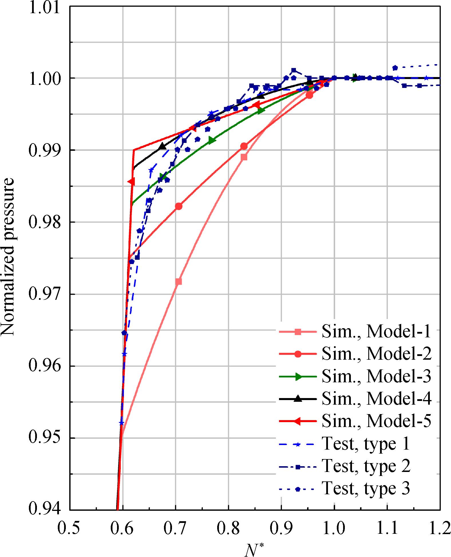
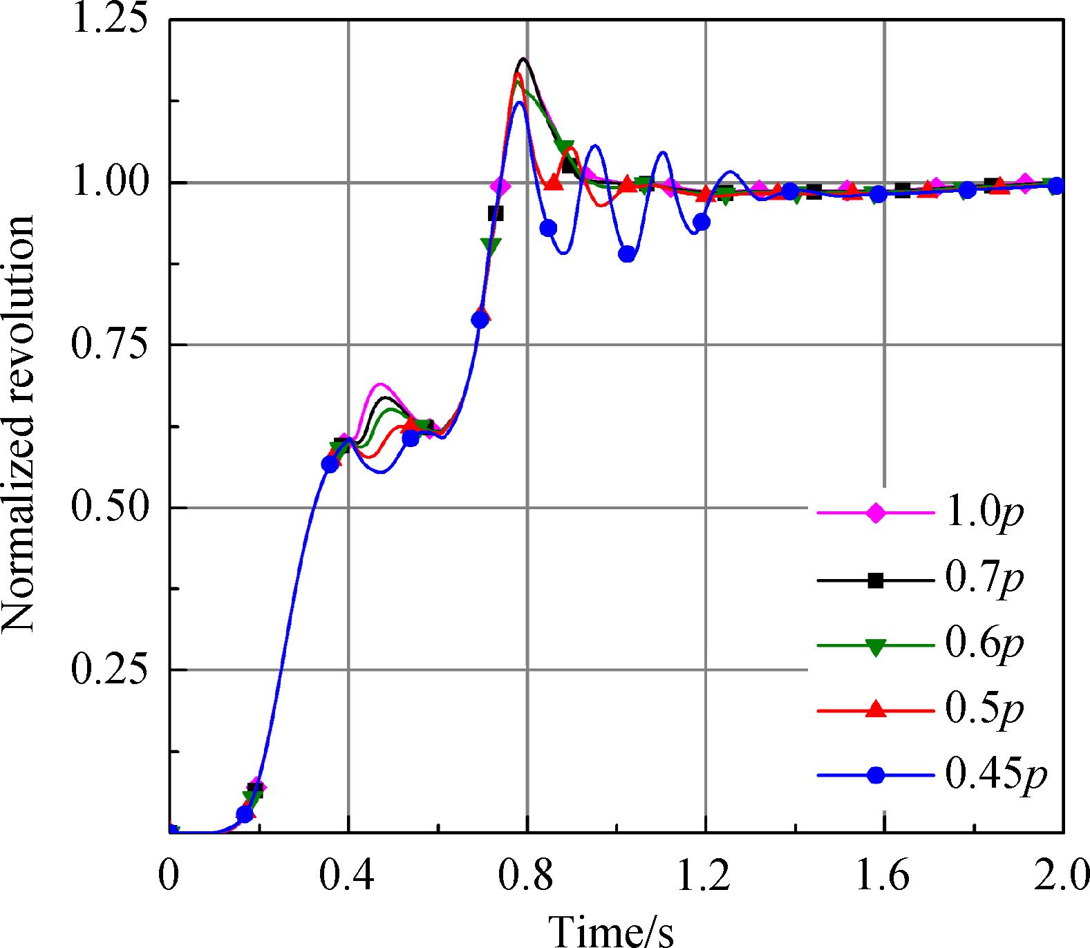
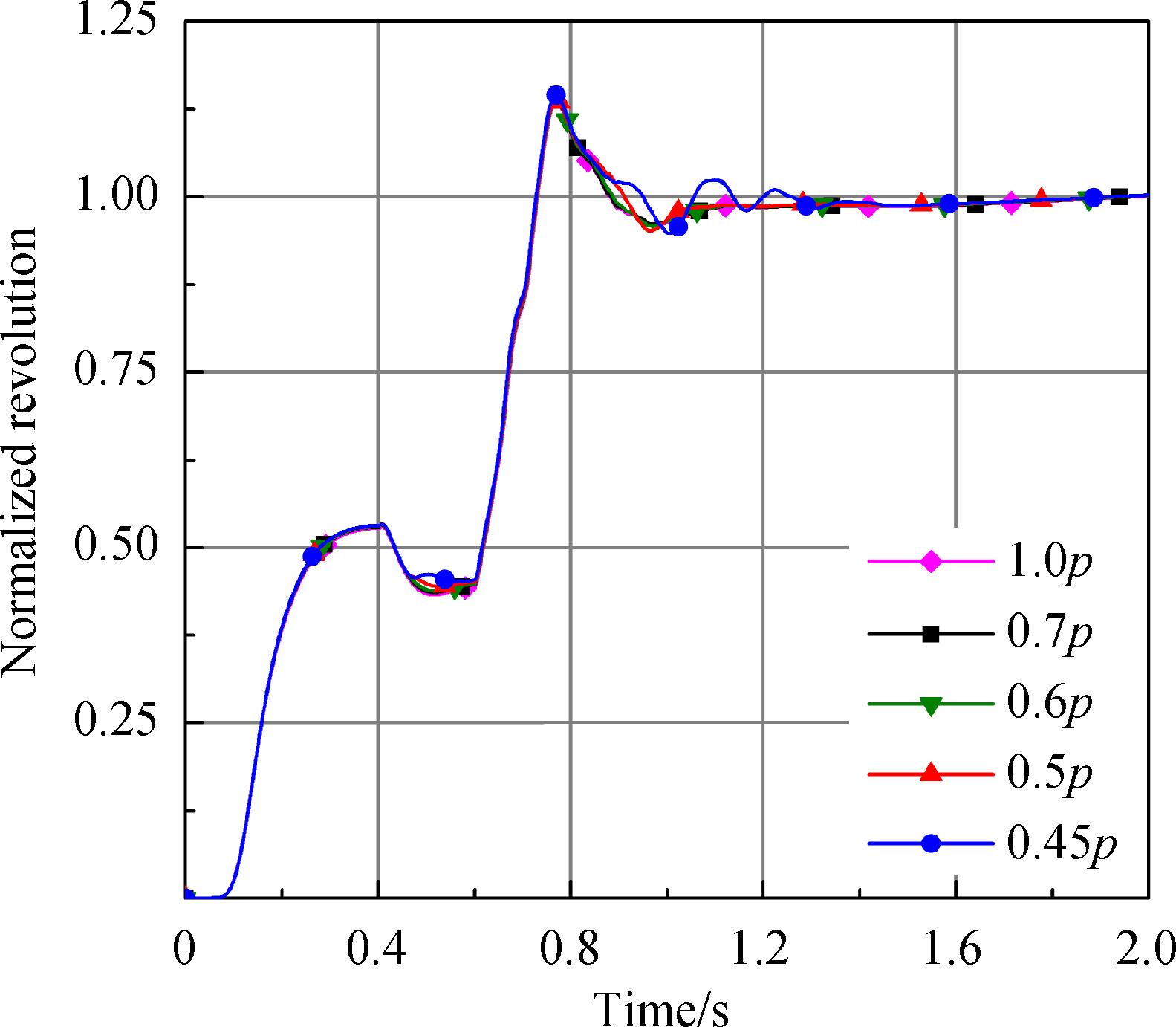
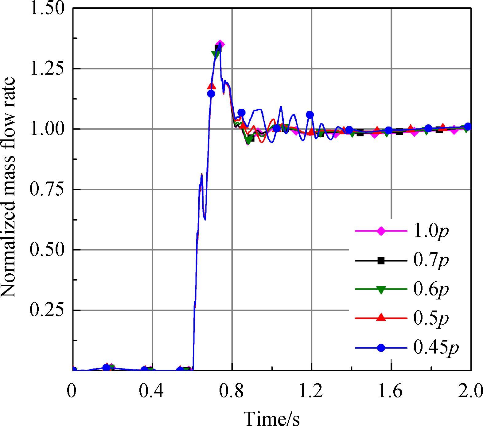
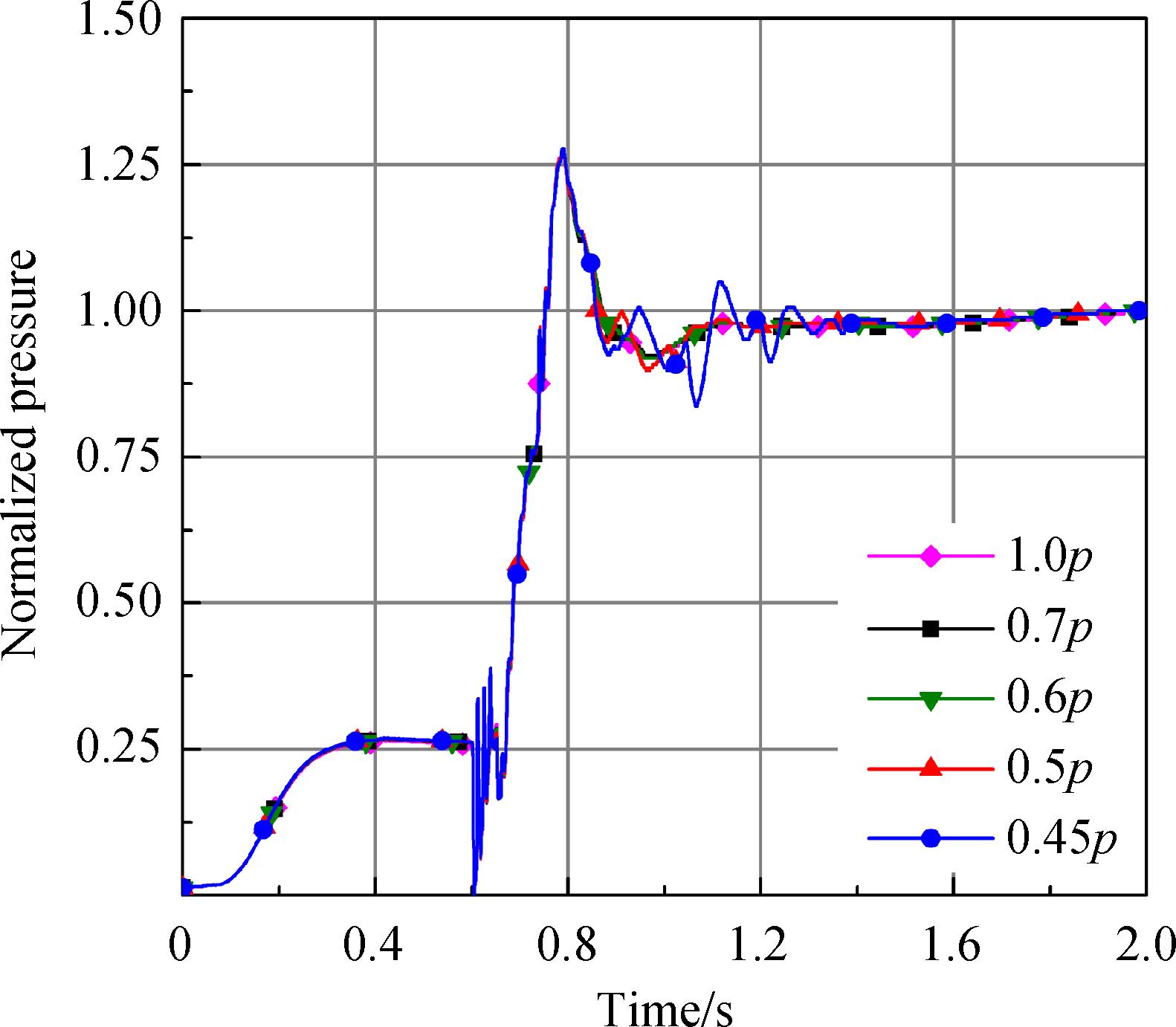
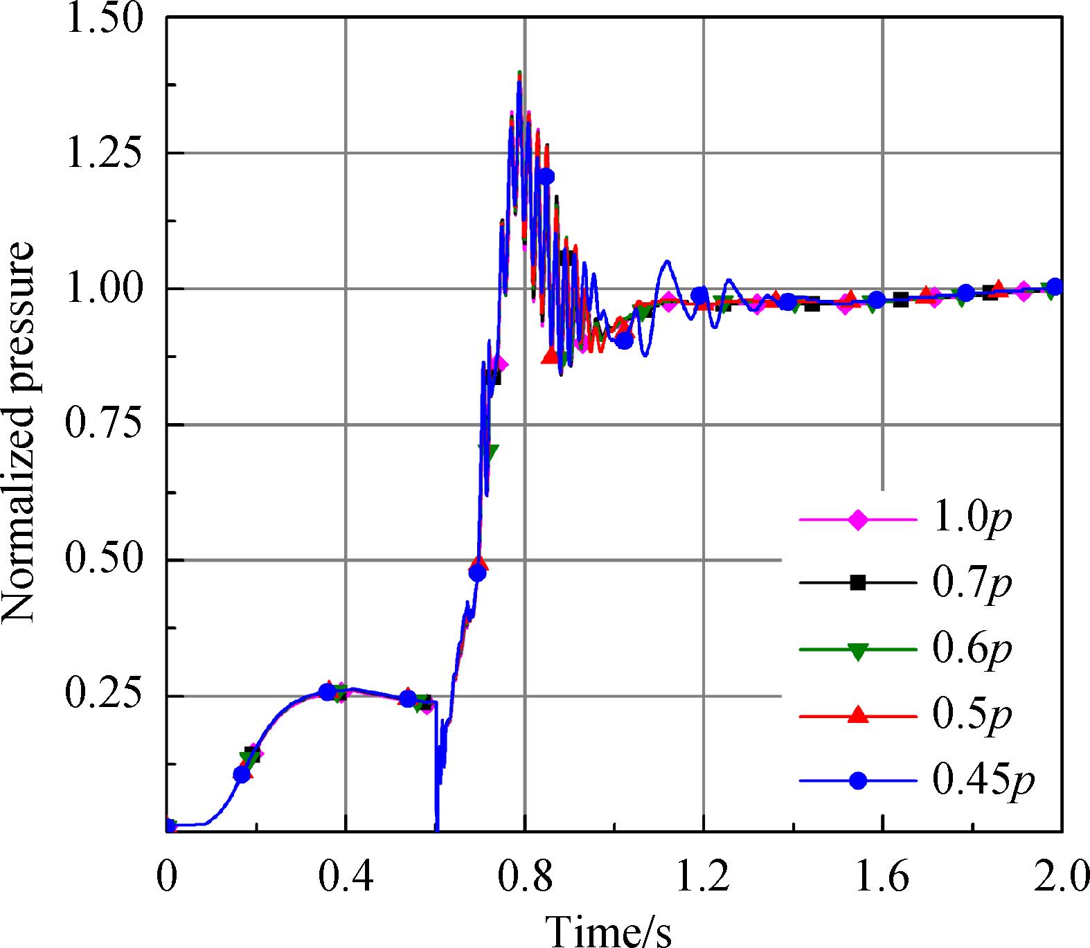
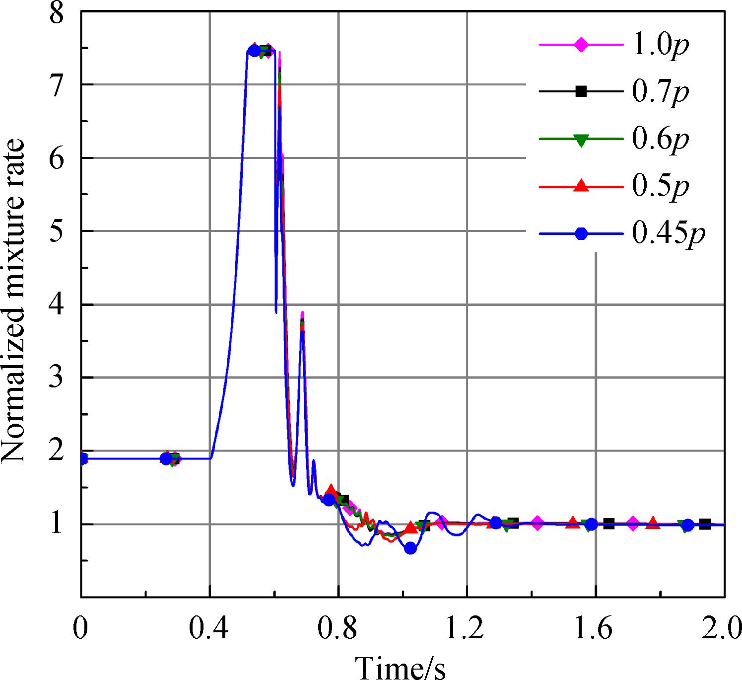
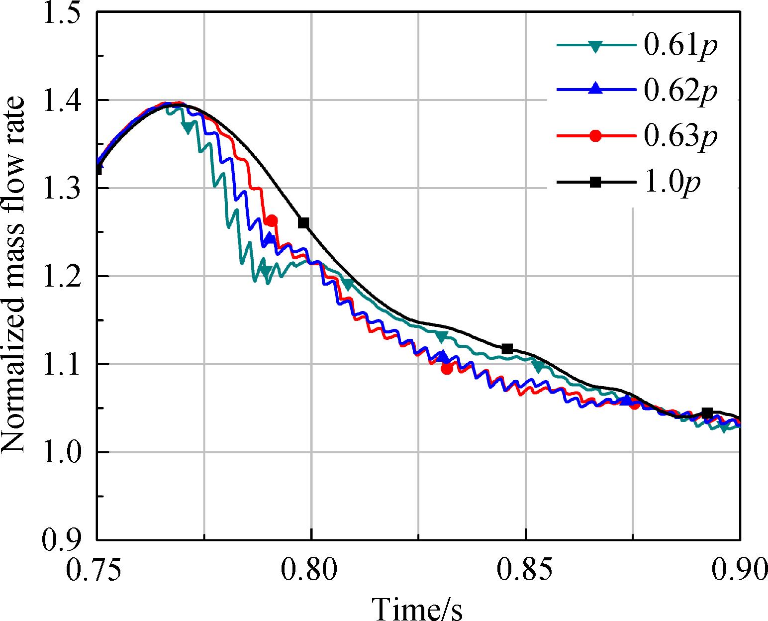
针对液体火箭发动机氧化剂泵的汽蚀过程,使用入口NPSH(net positive suction head)代替入口压力作为汽蚀发生的判据和入口质量流量的计算方法,并通过模型与试验结果的对比发现以扬程下降1.25%作为断裂汽蚀发生点的模型具有良好的精度。后续开展发动机低于额定入口压力的起动仿真,结果表明:62%及以上额定压力能够正常起动;45%及以下额定压力起动失败,原因是燃气发生器温度过高。主要存在0.4~0.6 s,0.4~0.85 s和0.4~1.2 s三个时间段的严重汽蚀,分别对应氧主阀打开、主涡轮转速的快速爬升和燃气发生器参数波动。氧化剂主泵汽蚀主要影响燃气发生器和推力室,次要影响燃料供应路组件,轻微影响主涡轮。
Abstract:The NPSH (net positive suction head) was used instead of the inlet pressure as the criterion of cavitation condition for liquid rocket engine cavitation process,and the model with the head drop of 1.25% as occurrence point of fracture cavitation had good prediction accuracy by comparing the simulation with the test results.Subsequently,the engine start⁃up simulation was performed.The results showed that the rated pressure of 62% and above can start normally;the rated pressure of 45% and below failed because the gas generator temperature was too high.There were three periods of severe cavitation in 0.4-0.6 s,0.4-0.85 s and 0.4-1.2 s,respectively,correspondingly to the opening of the main oxidant valve,the rapid climb of the main turbine speed and the fluctuation of the gas generator parameters.The cavitation of the oxygen main pump mainly affected the gas generator and the thrust chamber,secondly affected the fuel supply path assembly,and slightly affected the main turbine.
-
Key words:
- cavitation model /
- gas generator /
- start⁃up procedure /
- system simulation /
- liquid rocket engine
-
表 符号表
A/m2 等效流通面积 ps/Pa 液体蒸汽压 g/(m/s2) 质量场加速度 qm,pin/(kg/s) 泵入口质量流量 H* 无量纲扬程跌落系数 qm,pout/(kg/s) 泵出口质量流量 Cp/(1/m) 流体平动系数 Tf/K 流体温度 ml*/kg 泵内充满时的流体质量 Vc 无量纲空泡体积 n/(r/min) 转速 Δpp/Pa 泵正常工况扬程 N* 无量纲汽蚀余量 Δppc/Pa 泵汽蚀工况扬程 Nc/m 汽蚀余量 η 泵实际效率 Nc,cr/m 临界汽蚀余量 ηh 泵额定工况效率 pp.in/Pa 泵入口压力 ρ/(kg/m3) 液体密度 pp.out/Pa 泵出口压力 ξ/(1/m4) 流阻系数 p/Pa 额定起动压力  下载: 导出CSV
表 1 试验工况表
Table 1. Test working condition list
泵型号 试验转速/(r/min) 工质温度/K 工质密度/(g/cm3) Type1 6 459 302.85 1 Type2 5 991 304.05 1 Type3 12 997 301.25 1
下载: 导出CSV
-
[1] Беляев Е Н,Черваков В В.Математическое модеирование рабочего процесса жидкостных ракетных двигатей[M].Москва:Издательство МАИ⁃ПРИНТ,2009.(in Russia) [2] 契万诺夫Β Κ,比利亚耶夫Ε Η,切尔瓦科夫Β Β.液体火箭发动机工作过程的数学模拟[M].张兴波,李平,陈建华,译.西安:航天科技集团公司第十一研究所,2000. [3] BRENNEN C E.Hydrodynamics of pumps[M].Cambridge,UK:Cambridge University Press,2011. [4] BRENNEN C E.Cavitation and bubble dynamics[M].Cambridge,UK:Cambridge University Press,2013. [5] BAKIR F,REY R,GERBER A G,et al.Numerical and experimental investigations of the cavitating behavior of an inducer[J].International Journal of Rotating Machinery,2004,10(1):15⁃25. [6] 古里希 J F.离心泵[M].周岭,施卫东,译.北京:机械工程出版社,2019. [7] SHANG Z,EMERSON D R,GU X.Numerical investigation of cavitation around a high speed submarine using OpenFOAM with LES[J].International Journal of Computational Methods,2012,9(9):1⁃14. [8] BRENNEN C.Bubbly flow model for the dynamic characteristics of cavitating inducers[J].Journal of Fluid Mechanics ,1978,89(2):223⁃240. [9] 格列克曼 В Ф.液体火箭发动机自动调节[M].顾明初,郁明桂,邱明煜,译.北京:宇航出版社,1995. [10] KALNIN V M,SHESTERYANIKOV V A.Dynamic of cavitational failure of rotary pump[M].Moscow,Russia:MAI Publications,1976. [11] KAZIOLKOV B P,EFIMOCHKIN A F.Cavitation mechanism of rotary pumps in nonstationary regime[M].Moscow,Russia:MAI Publications,1972. [12] ZAKHAROV O V.Cavitation problem in rotary pumps[M].Moscow,Russia:MAI Publications,1967. [13] PILIPENKO V V.Cavitational auto‑oscillation[M].Moscow,Russia:MAI Publications 1989. [14] ZADONCEV V A,PILIPENKO V V.Specification of propagation of cavitational autooscillation in rotary pumps[M].Moscow,Russia:MAI Publications,1976. [15] PRISNYAKOV V F,PRON L V,SEREBRYANSKIJ V N.The dynamic model of failures in a liquid propellant rocket engine[R].Graz,Austria:the 44th International Astronautical Federation Congress,1993. [16] SHEVYAKOV A A.Theory of control automatic of rocket engines[M].Moscow,Russia:MAI Publications,1978. [17] 李龙贤,丁振晓,吴玉珍.基于热力学修正的诱导轮空化模型研究[J].火箭推进,2019,45(5):52⁃58.LI Longxian,DING Zhenxiao,WU Yuzhen.Research on cryogenicinducer cavitation model modified by thermodynamic effect[J].Journal of Rocket Propulsion,2019,45(5):52‑58.(in Chinese) [18] RAMESH D,ALIMOHAMMDI H.Simulation of cavitation process in oxidizer pump of a liquid rocket engine[R].AIAA 2009⁃4958,2009. [19] KUMAR P,SAINI R P.Study of cavitation in hydro turbines:a review[J].Renewable and Sustainable Energy Reviews,2010,14(1):374⁃383. [20] LUO X,JIN B,TSUJIMOTO Y.A review of cavitation in hydraulic machinery[J].Journal of Hydrodynamics,2016,28(3):335⁃358. [21] WASHIO S.Recent developments in cavitation mechanisms:a guide for scientists and engineers[M].Sawston,UK:Woodhead Publishing,2014. [22] RAMESH D,M.Nonlinear AMINPOOR,dynamic simulation of an open cycle liquid rocket engine[R].AIAA 2007⁃5507,2007. [23] FRANCESCO D M.Modelling and simulation of liquid rocket engine ignition transients[D].Rome:Sapienza University of Rome,2011. [24] 陈宏玉,刘红军,陈建华.补燃发动机强迫起动过程[J].航空动力学报,2015,30(12):3010⁃3016.CHEN Hongyu,LIU Hongjun,CHEN Jianhua.Forced start⁃up procedure of a staged combustion cycle engine[J].Journal of Aerospace Power,2015,30(12):3010⁃3016.(in Chinese) [25] BELIAEV E N,CHEVANOV V K,CHERVAKOV V V.Mathematical modeling of working processes of liquid propellant rocket engines[M].Москва:Издательство МАИ⁃ПРИНТ,1999.(in Russia) [26] 张贵田.高压补燃液氧煤油发动机[M].北京:国防工业出版社,2005. -


 点击查看大图

计量
- 文章访问数: 184
- HTML浏览量: 63
- PDF量: 79
- 被引次数: 0